
Having listened to push-pull amplifiers all along and very satisfied with the sound quality, because to me a tube amp sounds like a tube amp no matter what, I decided to try to build a single ended tube amp.
I start with an old Montgomery Ward mini console. I gutted out the electronics and pulled the necessary components. That is, I took out the power transformer and the audio output transformers. They are pretty average quality components.
The output transformer is set for 4 ohm speakers. They are made for 7868 pentodes, which have a recommended load impedance of about 2500 to 3000 ohms, so I figure that that is what the primary is. I am using 6L6's which are made for about 4500 ohm loads so I am pushing them a little hard. I can upgrade to Kt66's which are made for the lower load impedance.
The power transformer seems to be a 1:1 winding,
so I get 120 volts out for 120 volts in. The original circuit is a doubler,
and I kept that arrangement. The rectifiers are solid state. This is the
schematic for the power supply. I may use a tube diode for the doubler,
but I kind of like the idea of a low voltage loss across the diode. Tube
diodes have the tendency to drop up to fifty volts. This is why so many
claim that one diode tube "sounds" better than another. A different tube
actually screws up the bias to the point where the amp is likely distorting
more, giving that sweet second harmonic distortion. With a solid state
diode I get more voltage from the transformer to be used by my circuit.
It is a little more efficient. But again, this will be covered in the tech
section. Also, I am of the opinion that the power supply should add or
remove nothing from the sound quality of the amp.
This is the original doubler circuit. (Originally, my drawing had a couple of flaws. Special thanks to John Byrns for his pointing it out to me. The above circuit is correct. I will add a capacitor across the top diode to further reduce switching noise). I have also included here the choke in the filter. The choke is about 1.5 henries. The resistor is for the voltage amp/driver stage.
POWER SUPPLY WOES
I put the choke in line with the B+ to lower the hum, because in my first experiment I got hum, but still got some. I then decided instead of using the 40 microfarad cap right after the rectifiers to use a 10 microfarad cap. I chose this value based on a personal rule of thumb. The first filter cap should be close to the 10% rule of thumb for frequency response, namely, the cap's reactance should be 10% of the load impedance for the desired frequency. In other words I calculated the load as being about 160 milliamps at 325 volts. This gives an impedance of about 2000 ohms. So I take 10% of that and calculate the capacitance value by the equation 1/(2*Pi*f*Xc) or 1/(2*3.14*120*200). This came out to about 6.6 microfarads. I had a 10 available. Then after the choke I used a 40 microfarad cap and after a 40 ohm resistor I used a 100 microfarad cap. No hum whatever!
Before using the final power supply configuration, the sound was a bit high ended with a very noticeable drop in overall sound quality when a strong transient bass line or kick drum occurred. The midrange was very muddy, or lower end intense, or dark. This is usually confused or considered as warmth or fatness. Being a purist, I feel that it is coloration. After the power supply problems had been fixed, the sound became more balanced. I still got a nice warmth and fatness, but not overbearing. The high end came down to a normal level, and I got deeper bass. The first test was with a real good pair of headphones. Speaker test will be discussed soon.
I first used the 12AX7,but wanted to make this one with more vintage tubes. since the 6L6 was first made in the late thirties, it would behoove me to use a driver stage from the same period. I chose the 6SL7. I had to hard wire a keyed 8 pin (octal) socket to individually plug the wires into the respective holes of the 9 pin miniature socket. It is a forties tube that looks like it had never been used. I bought it from a friend who had a bag full of tubes. How does it sound? WOOOOW!!!! is all I could say when I heard it. The first thing I noticed was an increase in low bass. Then an interesting thing happened. The instruments began to sing to me, not just play. That's right, I said SING. This even from what I consider to be one of the worst recorded CD's I have in my collection. The highs seemed as clean as anything. I heard instruments that I didn't think were in there. I continued to hear those instruments even though the rest of the music overshadowed it. There was the lower mid range emphasis, but not too much where one would call it color, but a seemingly natural one. The crescendo's were typical of tubes, high in upper midrange, but again, they sang to me. I had honestly never experienced this before. I thought to myself, oh, so that is what second harmonic distortion sounds like. But then I realized that I had a TON of NFB. The distortion should have been at least below 0.5 % (I have no test equipment for that. Sorry. But I plan to use Steve Bench's poor man's THD tester), especially at the volume level to which I was listening. But this was from that vintage tube. Of course the singing I heard is not conducive to the purist in me, but what the heck, I like what I heard.
I am now wondering about the state of hi-fi back then and why it wasn't any better than it is now. With the deep bass, clean mids and highs I hear from this one tube alone (the 6SL7), it is a wonder that stereo, hi end audio, and the utmost in high fidelity hadn't reached its peak in the forties, instead of now.
On the other hand, I had always marveled at how good a sound I hear from one of the recording mediums they had in those days, film. In particular cartoons. I guess since they are not real but only animation, sound was an important factor in making one get involved with ole Bugs or Popeye. The sound on those old cartoons is in my opinion phenomenal, considering the time. I have my stereo VCR hooked up to my stereo system. Even some mid thirties films sounded pretty surprisingly good.
Now for the speaker test. I first hooked my mid/high speaker to the thing just to see how it would perform with speakers. My headphones are efficient, so the volume is loud in them. Speakers tend to be a lot lower (not just because the element is next to my ear, as I will explain later). I was truly amazed at the clarity and power of the amp at driving these speakers. If I had my woofers also connected, the volume and power would have shaken the house. I had the volume turned all the way up and the sound was as clean as ever. No audible clipping distortion, if it even reached clipping at all. A 2 volt RMS signal from the CD at full volume could only reach 20 volts at the primary of the transformer anyway (with a gain of ten), so the speaker couldn't be getting that much voltage at all. In fact, it measured about 1 volt at the peaks! But it was plenty loud. This from a secondary impedance of 4 ohms. The speakers were 8! The speakers have an efficiency of about 89 dB/watt, also.
I then hooked the amp up to its original home, the mini console. Its woofers are about 96dB/watt efficient. The mid/highs are a pair of relatively efficient (about 91dB/watt) car speakers. Loud and fidelity are two words that first come to mind. I get a sound that puts the EICO to shame! (One must consider though that the EICO output trannies have an 8 and 16 ohm tap, not a 4 ohm tap). This thing put out some bass that could really be heard! I don't think that I need to use the EICO as a bass amp now.
The imaging is surprising. Midrange is nice and clean. Bass, again, is surprisingly deep and present. The highs are also a surprise. I do not need to be right in front of the mid/high speakers to hear it.
All in all, when I want to hear a real nice sound, I will listen to this amp. But when I want to hear an uncolored natural sound, I will go back to my amp of my design. It is the SS amp that I speak of on the transistors pages.
THE COMPONENTS
I used newly purchased used but good RCA 6SL7's and brand new Tesla (now J/J's) 6L6GC's. I also got some nice amphenol ceramic sockets. I also made a minor adjustments to the biasing to make it more in line with the spec's of the tubes.
Instead of using a single 6SL7 for both channels, I used one per channel. I made a direct coupled common cathode voltage amp/cathode follower stage. According to some info I got from Steve Bench on his site, this produces a harmonic distortion of less than 1% without NFB using fixed bias. But I am using cathode bias. Hopefully, my distortion will be low enough. With NFB it should bring it far lower.
I constructed the chassis on a 1"X12"X24" piece of shelf. I started by putting the feet on so as not to scratch my table. I marked the locations of the tubes and the transformers. I screwed in the choke.
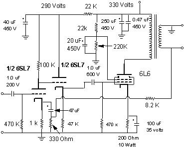
Here is the schematic of the amp as I originally constructed:

I have completed the amp above with but a few modifications. For the most part, the bias points were as predicted. I am actually surprised to a degree. The cathode bias at the first half of the 6SL7 is at about 1.25 volts, which makes the now 100K plate resistor drop 125 volts. So there is about 140 volts at the plate. The B+ at the other side of the resistor is about 290 volts. This is fine for my purpose. I am a perfectionist but not that much. Notice no bypass cap there at the 1K resistor. I do not need it. I also reduce a source of distortion. Gain is plenty.
The voltage drop across the cathode resistor of the 6L6 is about 12.5 volts It seems right on the mark! The RCA manual calls for that voltage for a fixed bias class A amp. The plate voltage is about 315 volts. B+ is about 325 or so. I had to make a change in the voltage divider for the grid 2 voltage. I was only getting about 160 volts. I reduced the upper one from 100K to 22 K. It brought the G2 from the 150 to about 230. This is close to the mark and caused the cathode to go to 12.5, where it was at 8 volts before. I got some more gain that way. Power supply capacitance is only about 250 microfarads. I get no ripple or hash or anything. I may not bother with the computer grade 350 mikes from my friend. But I might. I also used less capacitance for the driver, but I isolate the driver stages by using a 22K resistor for each stage. This might be known as split filtering. So each driver stage gets its own 290 volts and 40 microfarads of filtering, in effect. It is as close to separate power supplies as one can get without the extra real estate and expense.
The last thing I did was to go against my own philosophy, but I think it is needed for impedance purposes. I bypassed the cathode resistors for the 6L6's with 470 microfarad caps. A bit much I know considering that many of the schematics I have seen call for a 20 to 50 microfarad cap there. But using the 1/2pifXc formula I come up with about 330 microfarad for an impedance of about 20 ohms for 20 Hertz. Using the ole rule of thumb of 10% of the bypassed resistance, 470 uF was the closest ones I had on hand that would do the trick. I get a little more gain with no sonic disadvantages. In other words I get no lag or compression.
I use a 22K resistor instead of 10K in the feedback so as to get more gain. The gain should be about 23. I haven't fully calculated open loop gain, but I estimate it currently at about 96, assumning a gain of about 12 for the driver stage and a gain of about 8 for the power stage. Also I may seemingly lose damping but this doesn't seem to bother the sound I get. It is not perceptible. I have yet to test this amp on my acoustic suspension speakers, though.
This assumes of course alot. I do not know the load impedance for the output transformers. I am assuming about 4K. Since I bypass the cathode resistors the cathode resistance is 1/Gm, or 1/.006 (transconductance being about 6000 uS) or 167 ohms. So, the paralleled plate resistance should be about quiescent plate resistance which is about 4861 ohms in parallel with 4000 ohms or about 2194 ohms divided by about 167 or about 13. I have a couple of formulae for this. One was provided by Steve Bench (the one I just used) and the other two which are similar are from the RCA manual and an old text book from my school days. I cant remember them but they are a little more complicated than the neat one Steve showed me. The one from Steve is similar to what I have used for years in my solid state designs which shows the relation ship between the emitter (cathode) resistor and the collector (plate) resistor. In other words, gain could be calculated by this equation: G= Rc/Re, or Rp/Rk. however, for a tube Rp is the plate resistaoce in parallel with the load resistance in parallel with the next stage resistance. Cathode resistance is calculated by the reciprocal of transconductance in parallel with cathode resistor. For a transistor, the collector impedance is considered theoretically too high to bother, and the emitter resistance too low to care. But that is for the biasing page.
The gain of the driver stage should then be about 18, assuming the above equations and that the grid of the second half of the tube is over a few megohms of impedance. So given the calculated gains the overall open loop gain should be about 234. The best way to calculate it is as an old saying goes " why calculate what you can measure?" I will measure the output voltage and the input voltage and divide. I may or may not do this, but it is the easiest way to calculate gain.
Here is the final schematic:

(correction: I currently do not use the capacitor in the feedback loop.
It will be a 0.0033 uF not 0.01 uF when I do)
SUBJECTIVE TEST
For what it is worth, I do not know what the distortion rating is and do not wish to do the rigorous math as Mr. Bench does on his site to figure it out. I prefer the listening test myself. After all, I have played with ultra low distortion amps and have found that all things being equal, they do not necessarily all sound as good! I have replaced bipolar op-amps with equaly if not better distortion rated bi-fet op-amps and the bi-fets sound better with 0.005% distortion rating! SO... so much for objective tests.
This amp uses the cathode follower design because it is the lowest distortion amp for the easiest circuit topology. I also did not wish to use one tube for both amps to reduce crosstalk (increase separation). I use the beam power tube in beam power tube mode as opposed to triode mode because I want power. I believe that tubes sound like tubes regardless.
I powered up the bugger and began listening right away. No warm up time here, buster. The sound was far better than I expected. As you recall from above, I originally used the 7868 pentode. It sounded real good. I also used one 6SL7 for both channels. The first thing I noticed was an amazing clarity and distinction in each instrument. Then of course the typical tube "full sound". Remember, I used circuitry that is supposedly low in distortion and NFB.
Bass and treble are as the prototype, very present. I was intrigued by the mid range though. Not that it was so much as many who talk about the euphonics of single ended triode amps, but that it varied in its peakiness with material used. This suggested to me that the amp is relatively transparent. In other words it was not adding too much of its own signature to the source material. I guess I done good! Where the voice peaked aroung 500 or 600 hertz or so was noticed, as opposed to the first prototype which made everything sound warm. Source material that was made with tube amps (Abbey Road and The White Album from The Beatles) sounded very clear and had warmth but, as a freind described about my solid state designs regarding treble, it is "right there". Not too much and not too little, but just right.
Separation is very wide. Imaging is also very impressive. Sitting about seven feet in front of the five foot wide console housing the speakers one can "hear" a soundstage well beyond the walls, which are twelve feet apart. Some instruments seem to be right beside me, too. I am also amazed at the revealing of it. I hear more subtleties that I didn't before. On the other hand, I haven't listened to the White Album in years. Voices, both male and female, sound live. Whitney Houston was sitting on my lap seranading me. The backup singers were all around me.
All in all, this SE amp has truly impressed me to the benefits of class A SE amplification. Using the 6L6 allows for a tighter deep bass due to its stronger third harmonic while maintaining a good balance with a strong second harmonic from the 6SL7.
09-08-99
Before continuing with my push pull amp, I decided, since I listen to this amp while dorking in my shop, to do some bandwidth expanding. all I did was to add the cathode bypass in the output and add some bypass to the input. I did this more to add overall gain since I am not going to use a preamp per se. I am building a phono preamp to add to this amp, but am using the SE amp as is with no pre. A gain of 10 is insufficient for this purpose. Adding the bypass and setting NFB to about 30 should be good enough for most line level inputs.
In the process of lowering the added gain from bypassing the NFB should also increase the bandwidth. Given the medium quality of the transformers, I should be able to extend the response somewhat in both directions.
Here is the resultant schematic:
Notice the changes. I added the 100 uF caps to the cathodes of the 6L6's, and a 47uF cap and 330 ohm resistor in series as a semi bypass. This allows for some degenerative feedback at the 6SL7 while bypassing for a gain increase to about 40. The 6L6's gain now increases to about 10. So, assuming this is correct, I now have an overall gain of about 300, which I set back to about 25. So if frequency response looked like this before NFB:

It should now look something like this:

So, sure, I lose gain, but I get flatter response and extended frequency range.The flatter response also comes with less distortion.
How does it sound? To be honest, I expected to lose some of the charm of SE amplification with no NFB. But boy was I wrong. Not only did sound quality clear up, and I got more revelation, but the sound actually seemed more natural warm and sing-like like my first experiment above with the 6SL7. I was truly taken aback. I wonder if the response is because of the better damping? I don't know, but I do like what I hear. I played First Band on the Moon by the Cardigans, September my Years by Frank Sinatra (the instrumentation sounded very live), Magical Mystery Tour by the Beatles, The Greated Hits of Emerson Lake and Palmer, and the first cut of the Wall by Pink Floyd. I don't know what it is, because I do not try to make this amp improve the sound quality of these sources, but evrything sounds great through this amp, even better than before.
Here is an actual picture of the almost finished product:

Power is on, as you can see from the orange glow from the power switch on the lower right hand side of the board.
This is an overhead view of the power supply:

I kinda like this one myself (not tube? I am using solid state. See the black caps in the middle? They are part of the voltage doubler). I had such a difficult time deciding how to mount the filter caps. I did not get the 350 mFd computer grade ones because my local supplier had a ton of these cans. So I bought up a bunch rated from 40 to 100 mFd at 450 volts or better. As you can see i used an orange drop 0.47 mFd and found another source for 'lytics. The blue one above is a sprague 47 mFd at 450 volts.
Surprisingly, as I mentioned before, I get no hum. I do hear the power trannie buzz though, but I get no noise through the amp to the speakers. Just heavenly sound.
MORE UPDATE!!!
I recently acquired a few other 6SL7's. I got NOS JAN Phillips versions and a couple of Russian current production 6SL7's. At first listen the JANs were absolutely perfect. A good blend of full range and warmth. The way I like it. I am saving those for special listening binges. The Russians sounded bright and flat. No tubelike depth. But I seem to recall that that was typical. What I did not know and found out for myself and read later was that when they break in look out! I was using them exclusively for one week just because I was doing some work in my lab and one day, about four days later, I started hearing sounds that were very good. I was truly surprised becauseat first I though that I had put the JANs back in but to my pleasant surprise it was those cheap Russians in there. The Sovtek 6EU7's I got for my P-P amp also surprised me once they broke in. Very nice.
I also recently tried to play with this design to see if I can improve it even more. I think I did. The first think I did was to use the same NFB loop that was used in my P-P amp, where the signal goes back to a small value resistor that is in series with the actual cathode resistor. This first thing I noticed was that deep bass got deeper and stronger. I then played with the idea of connecting the cathodes in common. That is using the idea from the push pull amp I recently did and an idea I saw from Decware. The thought of this is that one tube can act as a fixed cathode source for the other side. Here is the schematic:

I find that both the high and low end has been extended a little. Again particularly the low end. Kick drums and deep bass notes are more pronounced. It is truly surprising. The warmth is still there, however, and, notice, this is with an amp where I employed NFB previously, there is even more detail. It is true that deployment of these tricks of the trade is an art. The use of one resistor for both channels gave the amp more depth of perception and separation. I attribute this to some of the signal from one channel bleeding in to the other and being out of phase with itself, sort of the way Dolby encoding works. I find now that I need to move around to find a sweet spot where the bass is just right throughout the range. I may remove the sharing of a common cathode resistor, or use a larger bypass cap. Another thing to do is to blend the channels together with a resistor from one input to the other.
Here is another wierd thing. The Russian 6SL7's sound better than the RCA's with this configuration, but the JAN Phillips are still the best.
I would say that this is a good argument for the employment of NFB. I do not know yet why indirectly applying NFB seems to have this dramatic a difference as opposed to directly applying it to the components. The sound, as I express on the second PP amp page, seems to transcend the limits of the output transformer. I strongly suggest that those who may be reluctant to use NFB because of the bad reputation that those who may or may not fully understand its purpose claim, that they at least try this particular combination as an experiment. All it takes is two resistors each channel. You may lose some gain but the results may make a believer out of you. It did for me.
Next I may drop the single voltage divider for the screens and give each output tube their own screen resistor without a filter. I also have been toying with the thought of connecting a capacitor from the screen to the plate, as sort of a pseudo ultralinear connection.
Next tube project will be to re-vamp my EICO 2536 Push-Pull.