
Technical Paper on LPG Pier, Tanjung Sulong, Malaysia
The pier which is designed by Sepakat Setia Perunding of Kuala Lumpur to serve 4,000- 40,000 dwt tankers (max. capacity 75,000 m3) is constructed by CNP as subcontractor to Toyo Engineering Corporation of Japan. The owner is Petroliam Nasional Berhad (PETRONAS).
General
The pier comprises a single berth of four breasting dolphins, four mooring dolphins and walkway support structures placed symmetrically about a central loading platform. This platform is served by an approach trestle of 291 metres in length with its longitudinal axis normal to the shoreline but skewed at 45 degs to the berthing line. The structures are all in reinforced concrete supported on tubular steel piles varying from 600 to 1000 mm in diameter. The outer sections of the pier were constructed in a basin pre-dredged to -14.0 m ACD as a part of the overall dredging scheme for the harbour.
An unusual feature of the design is the degree of continuity provided between structures bv the use of encasted steel. The breasting dolphins are all linked to each other and in turn to the loading platform. Similarly, the walkways are fixed over the full length from the big breasting dolphin (B.B.D.) to the outermost mooring dolphin (M.D.).
View of LPG Pier from the seaward side (mooring dolphins not visible)
Piles
The area is one of complex geological activity which limited soils investigation data indicated to be highly variable deposits of marine sediments generally overlying shales and sandstones. The depths at which sands, clays and silts were encountered were totally inconsistent.
None of this precluded the main contractor from adopting the concept of having all piles fabricated in single lengths in Japan for delivery by sea.
Grade 50B high yield steel spirally welded tubular sections were provided for piles in lengths ranging from 24 to 37 metres with similar sections up to 39.6 metres long as structural steelwork.
In all 1,195 tonnes of tubular steel were offloaded by ship's derrick from the m.v. "Sacramento" onto three 120' x 40' flat top pontoons in the open sea some 1,500 metres off Tanjung Berhala harbour.
Piles were driven open ended and without pile shoes by Kobe K45 and KB60 diesel hammers to the required ultimate driving resistance of twice the working load, as determined by the Hiley formula. Penetrations ranging from 10.5 m to 25.0 m were obtained.
The approach trestle comprises 16 bents of 19.4 m centres of which 14 are identical 3-pile bents made up of a pair of piles raking at 1:4 and opposing 15 degs skew and an independent vertical pile. The two bents at the extreme shoreward and seaward ends contain three and two vertical piles respectively. All of these piles are 700 OD x 12 mm wall thickness.
It was originally conceived that the first four bents would be driven from the shore. By judicious timing it proved possible to pile both bents 4 and 3 by barge at High Water Springs.
20 No. 900 OD x 12 mm wall piles were driven in the central platform on a 6.0 m x 6.5/7.0 m grid. Two pairs of raking piles carry transverse berthing forces and a further two pairs provide resistance to horizontal forces parallel to the berthing line. Piles in the big and small breasting dolphins were airlifted to -20 m ACD, pumped dry and filled with concrete hearting to superstructure soffit level. Six I,000 OD x 16 mm wall and four 900 OD x 16 mm wall piles were provided in each B.B.D. and S.B.D. respectively.
Each mooring dolphin comprises a group of six 60(l OD x 12 mm wall piles raking at 1:3. The four piles in each group to be anchored were airlifted, pumped dry and filled with hearting concrete. Intermediate supports for the walkways were also of the same section.
There are a total of 123 piles in the jettv of which 86 are rakers.
In view of the substantial penetration achieved, it was decided to dispense with any horizontal or vertical pile bracing, some piles remaining unrestrained for over six months without sign of distress. No temporary piles were necessary to assist the construction.
Ground Anchors
Some time after completion of piling we were instructed to install tension anchors in 22 of the piles, four in each of the mooring dolphins and three in each big breasting dolphin.
The design requirement was for 100 tonnes and 120 tonnes anchors to be provided by stressed wire tendons comprising 13 and 15 seven-wire strands respectively of 12.7 mm diameter. The strand was supplied with a factory applied grease and polyethylene sheath to provide corrosion resistance over the free length.
This type of anchor differs from the more conventional UC section "pin" arrangement, in that the anchorage is formed in the superstructure supported by the pile(s) and not within the toe of the pile itself. The anchoring operations can therefore only take place after completion, or partial completion of the superstructure.
A 200 ID permanent steel casing fabricated in two 12-metre lengths with centralisers and extending to top of concrete level was inserted into a pile on completion of dewatering and encased by hearting concrete.
The extremely small plan dimensions and pile configuration of the mooring dolphins dictated that the anchorages be placed approximately one metre above the soffit. A cantilevered steel frame temporarily fixed to the structure at this level served as the drilling platform.

Mooring Dolphin - installation of ground anchor in progress
A 165 mm diameter hole was drilled beyond toe of permanent casing and pile to permit a nominal fixed (bonded) length of anchor of 10 metres to be achieved. It proved necessary to advance a temporary casing to bedrock in every pile due to the weak strata. Both a Hongdrill HD30 and the larger Bachy SRI 00 rig were used to drill to depths of up to 61 metres below table. Drilling was carried out by both tricone and Atlas Copco down-the-hole percussion bits.
Strand and grout conductor were fabricated to length on the support barge and placed into the empty drill hole prior to primary grouting which was carried out in two stages using ordinary portland cement and a 0.5 water-cement ratio. Pressures of up to 30 kg/cm2 were employed in the second stage.
On achieving a grout strength of 17 N/mm2 stressing to working load was permitted using a PSC Titan mono-jack followed by secondary grouting of the free length.
Pile Tests
One compression test and two tension tests were carried out on working piles. A 450 tonnes static load test (to 1.5 times the working load) was conducted on a pile within the central platform with adjacent permanent works piles providing support for the grillage of steel beams and kentledge of concrete blocks. A single 600 tonnes jack was used and the readings of settlement carried out by vernier with a level fixed to an independent but restrained reference pile.
The tension anchor tests were conducted on a 100 tonne and a 150 tonne anchor at 1.2 times the working load in both cases. The residual force in the anchor measured 24 hours after loading when compared with the permissible values in British Standard Institution: DD81 - Draft for Development of Ground Anchorages, provided the criteria for acceptance of the anchor.
Sleeves
Additional resistance to corrosion within the splash zone from - 1.0 m ACD to superstructure soffit was provided by tubular steel sleeves of the same material and coating specification as the piles. With an outside diameter of 150 mm greater than the pile, each sleeve was threaded over and suspended from the rough-cut pile and the annular space sealed with cement grout as a non structural void filler. In addition the pier is provided with a galvanic anode cathodic protection system.
Approach Trestle
Each bent of the approach trestle carries an independent reinforced concrete pilecap for roadway and pipe deck. To accelerate construction approval was obtained to use a precast concrete shell as permanent formwork for the raker pilecap. Fixing for the unit was provided by two 203 x 203 UC cast into the walls of the shell bearing on and welded to the piles. The parallel roadway and pipe decks are made up of inverted tee beams spanning between pilecaps with mass concrete beam infill and in-situ topping to form a continuous structure. Eight beams support the four metres wide roadway and a further two the 0.9 metre wide pipe deck.
The 150 No. 18.9 m long prestressed beams were cast in an existing yard some 65 km away from site and transported by road, two beams per trailer. Grade 55 concrete was produced from a Winget 21/14 mixer. The beams were cast in steel forms and air cured prior to lifting after 3 days. An average production of 8 beams/week was achieved from four casting lines. Transverse pipeline support beams (P.S.B.) at approximately 4.5 m centres spanning between roadway and pipeline prestressed beams were cast in-situ together with diaphragms on each exposed longitudinal beam face. Similar 3.5 m long cantilever beams were provided for pipe loop supports at bents 5 and 12. Stainless steel insert plates and bolts were cast into each of the 60 P.S.B.'s to support pipe work and pipe racks.
Expansion joints are provided only at bent 6 and at the junction with the central platform.
Central Platform
The central platform is a two level structure with a 22 m x 20 m lower deck which incorporates a light rendering system and serves as a vehicle turning bay, foundation for the two storey control house and carries knock-out drums, pumps and pipework distribution to the upper deck. This deck carries five gas loading arms and a fire monitor tower with attendant pipework and fittings. As originally designed the whole platform was of in-situ construction with the exception of ten perimeter pilecap units. The lower deck of beam and slab construction was to be integrally cast with in-situ extensions of the pilecap units together with low level beams interconnecting each perimeter pilecap. The latter would have required to be cast in the intertidal zone and there was clearly advantage in precasting as many as possible of the lower deck elements.
Cubic precast pilecaps with 2 m sides and a 1.3 m diameter hole about the vertical axis were threaded over and suspended from the pile head on wire strops pre-fabricated to suit positioning of the unit soffit at -1.0 m ACD. Bolted mild steel collars around the pile provided support for the shutter retaining concrete tremied into the annular space.
Approval was granted for the precast alternative subject to it following the general arrangement and appearance of the original. Thirty-eight beams ranging from 600 x 600 mm to 1650 x 1800 mm in cross section with a maximum weight of 24.5 tonnes were placed by the crane barge "Tyr" at low and high level positions with an in-situ "stitch" at each node. Starter bars for the eight 700 x 700 columns supporting the upper deck were cast into the appropriate precast beams. Spanning between the high level beams were three rows of thirteen prestressed slabs each 5.0 m x 1.2 m in plan.
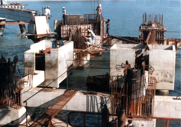
Central Platform - precast permanent formwork & pc beams in place
The 200 mm thick slabs containing 21 No. 12.7 mm dia. seven wire strand tendons in Grade 55 concrete were cast off site in the same yard as the prestressed beams. A 150 mm slab acting compositely with the prestressed concrete slabs was poured in three bays to complete the lower deck.
The 22.0 m x 10.0 m heavily reinforced beam and slab upper deck was concreted in a single pour together with the staircase to the lower deck. After completion of the main structures, numerous insert plates and plinths were cast in both decks for equipment foundations.

Central Platform - construction in progress (note anchor sockets for rubber fenders at front precast pc pilecaps)
Breasting Dolphins
The big and small breasting dolphin structures followed the general design philosophy of the central platform of precast pilecaps and in-situ block above. The precast pilecaps partially support the lower cell of the I x 2 configuration Bridgestone cell fenders. SUC1600H and SUCIOOOH fenders are provided for the B.B.D.and S.B.D. installations respectively.
The precast concrete units generally followed the pattern of those on the central platform and were installed in a similar manner. For symmetry, the S.B.D. units fitted over two vertical piles requiring a unit of 4.0 m x 2.0 m x 2.0 m with an all-up weight of 25.5 tonnes.
The soffit and falsework of the in-situ cap was supported by 12 mm thick m.s. collars bolted around each pile. The design soffit level was again in the intertidal zone which consequently dictated construction methods and timing. An initial 600 mm lift secured the soffit from wave action and provided support for the remaining 2.9 m height which was cast in a single lift at a controlled rate of pour.
Mooring Dolphins
Construction of these structures, octagonal in plan with a 3.7 m width and 1.8 m depth had to be carried out in two stages to permit the installation of ground anchors.
Stage I provided a one metre deep cap with a recessed and splayed surface normal to the axis of each of the six supporting piles to provide bearing for the anchorage head of each tension anchor. Box-outs were also required to accommodate walkway tubes.
After satisfactory stressing of the anchors and placing of walkway tubes, Stage 2 was cast to finished deck level followed by the installation of 2 x 60 t quick release hooks and ancilliary equipment. Support for the soffit and hexagonal frame falsework of the Stage I pour was again provided by bolted steel collars around each pile.

Quick Release Hook mounted on mooring dolphin
Structural Steelwork
1000 OD x 16 mm wall coated high yield spirally welded steel tube spanning a maximum of 37 metres forms the principal member of each walkway supporting hard wood joists and planks via brackets welded to the upper face of the tube. Each tube butt welded in-situ at the intermediate support before being cast-in both there and each mooring dolphin.
600 OD and 320 OD tube of the same specification form the chords and diagonal respectively of a horizontal truss which spans between each S.B.D. and B.B.D. These trusses of 16.2 m length and 4.2 m width were fabricated in the East Wharf yard and positioned on mild steel saddles an knee braces which were welded to the S.B.D and B.B.D. piles and adjusted for line and level in advance. The truss ends were cast into the upper lift of the dolphin structures
Site Establishment
It was conceived from the outset that the LPG pier would make full use of the facilities and infrastructure already in existence for the East Wharf. Space in that yard was severely limited and a small additional area was used adjacent to the Export Terminal boundary to provide a labour camp, canteen, rebar yard and subsidiary precast yard.
As a result of a necessity to extend a number of the pile lengths provided, a storage and welding facility had to be quickly established on shore for which an area was made available under the 30 m wide tracks of the 50 t Carruthers gantries.
Precast pilecap units and beams were also cast beneath the gantries.
A load-out facility existed on one face of the caisson casting dock and was used to transfer piles, precast concrete units, prestressed concrete beams and slabs and sundry materials to transportation barges alongside. Use of this facility was severely limited during caisson casting operations for the East Wharf.
A narrow slip-way was constructed between the east Finger of the dock and the East Wharf retaining wall for loading/unloading concrete trucks from the ferry.
Plant
Principal floating plant was confined to the "Tyr", a 36 m x 18 m steel barge with 28 tons Butters derrick and "Brightgold" a 100' x 30' pontoon carrying a Link Belt LS-118 50 t capacity crane.
Following reports of suitability on the Gas Separation Plant pier project at Laem Chabang in Thailand a similar uniflote ro-ro fen-y with a 90 hp Schottel rudder-propellor was constructed for loading and transporting ready-mixed trucks. This unit proved to be highly manoeuvrable and versatile.
A further 100' x 30' pontoon with 35 t crane was mobilised as a support barge for the ground anchoring operation and the three chartered flat top pontoons for pile storage completed the marine list.
Maximum advantage was taken of placing concrete from completed portions of the works using shore access. An IHI IPF-80B truck mounted concrete pump with an 18 m boom and 10-60 m3/hr placing rate enabled the approach trestle, central platform and breasting dolphin superstructures to be concreted with greater flexibility than the constraints of marine transportation and placing normally permit. The pump was also transported by ferry and placed on the deck of the "Tyr" when tremie-concreting the central platform and breasting dolphin substructures.
The piling was carried out by a sub-contractor, Antara Koh Pte. Ltd., supplying a 120'x 56'x 8' steel dumb barge equipped with a 42.5 metre high backward/forward raking tower and single ram hydraulic cylinder. The shallow draught of the barge proved particularly advantageous over the inshore areas of the approach trestle.
Programme/Progress
The contract commenced in August 1983 with a period of 12 months for completion. Several intermediate key dates were required to be met during the course of the contract to give access to the mechanical contractors.
An important feature of the east coast climate is the much vaunted northeast monsoon which is generally believed to occur between November and February. Like most meteorological phenomena it is whimsical by nature and duly acknowledged last year's construction activity in the region by depositing the heaviest rainfall for the last twelve years. Precipitation apart, related meteorological activity in the South China Sea promotes a heavy ground swell which crashes on shore after its uninterrupted passage over 1,200 km of ocean.
The timing of contract award and a short contract period made it imperative to complete pile driving before the onset of the monsoon. The fast-tracking concept proved successful despite the delays occasioned by the requirement to lengthen piles and work was completed just before the monsoon closed in, preventing any further marine operations.
Production effectively re-commenced in February and progressed including the additional ground anchors to substantial completion in mid-November 1984, an effective period of ten months.

Mooring of tanker by hooks on Big Breasting Dolphin (foreground) and Mooring Dolphins