The exhaust system is always a hot topic. At 1-1/4" in diameter, not only is it undersized
and very restrictive for the 1275cc A-series engine, but it is a size no longer available at your local exhaust shop.
The original system can best be described as performance robbing, frail and problematic.
There is really no design consideration to absorb the rocking of the engine and therefore breaks and leaks are very common.
Modern front wheel drive cars employ either a swivel connection between the manifold and the header pipe, or a flexible connection positioned
just after the header pipe turns under the firewall and straightens out again. Many also employ motor mount configurations
and/or top mounted engine stabilizer bars to control engine movement.
The America's system pipe diameter is far smaller than should have ever been used.
In fact, under hard acceleration, the tailpipe usually emits a whistling or hissing sound. A dead give away of an overly
restrictive exhaust system. The smallest exhaust pipe diameter, and pipe bending equipement used in exhaust shops
in the USA is 1-1/2" diameter. So, there is no way to get the stock exhaust system repaired properly.
Here are pictures of the 2 systems that I've designed and had built for my car.
Both worked excellent and are a combination of the types of systems found on modern front wheel drive cars. I have installed
a top mounted engine steady bar, a flexible connection in the front exhaust pipe, and mounted the system in soft rubber hangers.
I've also done away with the original flared and clamped connection between the manifold and the header pipe. This connection
is a tremendous source of leaks and breaks. However, I did try to replicate the overall design of the original system,
in an attempt to keep a reasonably correct sound.
One word of caution on getting exhaust work done. Stay away from the national chains
that advertise lifetime warranty's. Their corporate "Bean Counters" have figured out that the average person keeps the
average car an average of 2-3 years. Therefore, the quality of parts and workmanship they provide is commensorate with
their beliefs. The only guarantee you get is that you'll be back many, many times.
Go to a reputable local exhaust shop, especially the one that seems to do alot of work
on the local custom car and street rod owner's cars. These guys know how to weld and they know how to install a nice
sounding and working system. Get your exhaust done right the first time. You won't regret it!
|
|
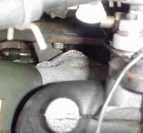
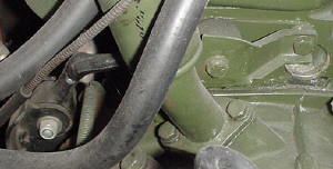
This is a view looking down the back of the engine from the right
side (clutch side) of the carburetor. You can see where the outlet portion of the exhaust manifold has had a oval
shaped 2 bolt flange slipped over it and welded in place. Your exhaust shop has these flanges pre-made in a variety
of sizes and configurations. We found a flange that had an inside diameter that fit over the outside diameter of the
manifold. It accepts a standard high quality exhaust gasket and has 2 bolts welded in place.
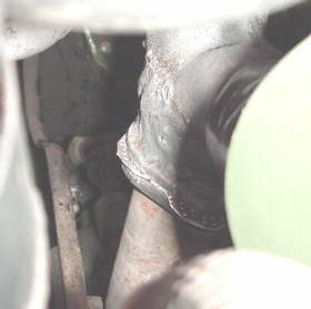
Here's a second view of the flange connection at the manifold looking
from the clutch side of the engine. Please note the wide weld bead used to weld the steel flange to the cast iron manifold.
Yes it is possible to weld cast iron...if you go to someone who knows what they're doing. Once the flange is welded
in place, take a die-grinder and grind out the inside of the exhaust manifold's outlet to increase it's internal diameter.
Any improvement here will greatly increase the flow of exhaust gases out of the manifold.
The new exhaust header pipe will be 1-1/2" in diameter and have a matching 2 bolt hole
flange welded to it. Once mated to the manifold flange with a gasket in place, you will install nuts an washers
from the bottom. It is easy to reach from underneath when the car is on the exhaust shop's rack. It
is also easy to reach from above the next time you have to remove the manifold for any reason. The best of
both worlds. The header pipe simply drops straight down at a slight angle to the backside of the axle flange.
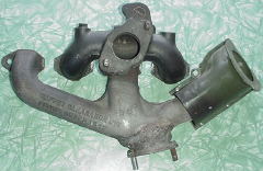
This is how the manifold looks with the 2 bolt flange welded in place. Notice how wide the
weld "bead" is. The guy who welded this for me has a been a welder for probably 60 years.
This view shows the upper engine stabilizer bar that I added to my engine. These bars
were originally used on America's that came with automatic transmissions. The bar has to be cut and re-welded or
heated and bent, into an "L" shape in order to clear the clutch slave cylinder on the manual transmission car. It helps
if you install the breather that's pictured in order to clear the mounting bolts for the stabilizer. I used polyurethane
bushings that are available. The mount is completely eliminates all engine movement, yet does not transfer any noise
or vibration because it is mounted to the subframe. It is a difficult job to mount the brackets that attach
to the subframe because they were originally installed when the subframes were out of the cars.
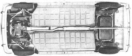
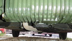
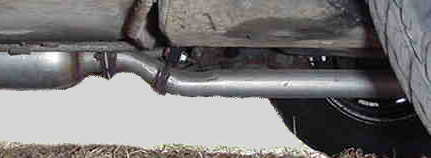
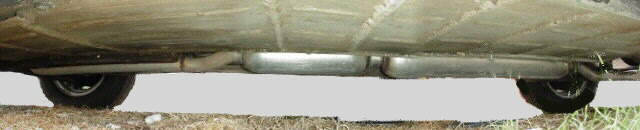
This view from the front looking back shows how straight the system
is under the car. There is plenty of room to run the front section of pipe down the tunnel on the right side of the
remote shift housing, just like the factory did. Keep the pipe up tight to the body by roughly keeping the center line
of the pipe lined up with the bottom of the remote housing. It won't hit anything that way, and it will look very clean,
professional and stock.
Once the pipe gets past the rear end of the remote housing, it can be curved into the
center of the tunnel and remain in that position all the way through the mufflers and out to the tail pipe.
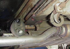
This view shows the header pipe as it turns and goes toward the rear
of the car. As the header pipe runs down the back of the engine, it passes to the rear of the right transmission output flange.
There should be a bracket at this location, mounted to the differential housing side cover using 2 of the sidecover bolts.
A standard horse-shoe shaped exhaust bracket can be used to hold the header pipe securely to the engine. You must have
this rigid mount at this location.
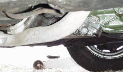
The 2 pictures above show the system as I originally designed it
and had it installed. I found a woven stainless steel flexible connector on a Japanese car in the local wrecking yard.
This is a great source for these flex pieces because they are extremely expensive at the exhaust shops. This flex piece
was a bit too big, but the price was right and it performed well. I would recommend using one of the smaller flex pieces
like those used on the Mitsubishi's or Geo's. Many of them are more like the size and shape of a slightly flatened baseball.
Following the flex piece is a high quality glasspack. It is 2" inside diameter,
4" outside diameter and 24" long. You'll have a choice to turn the glasspack so the internal louvers face into the flow
of the exhaust or away from it. In otherwords, they will either scoop at the exhaust, making the system quieter, or
be facing away from the flow, making it slightly louder.
Just after the glasspack is another 2 bolt flanged connection. This is located just
before the rear subframe and allows the tailpipe section to be removed so that the fuel tank or rear subframe can be dropped
without dropping the entire exhaust. It also allows the system to be replaced or repaired in sections that unbolt.
There is a soft rubber hanger located in the original position on the front of the subframe.
Make sure this is soft rubber and not one of the reinforced rubber hangers that look like a section of tire belting.
The system needs to be able to flex. A second hanger is placed on the rear crossmember of the rear subframe.
It also must be soft rubber.
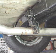
This view shows the front mount on the rear subframe is simply 2 "L" shaped brackets welded in place.
One is welded to the subframe and the other is welded to the exhaust pipe. These have flared ends where they locate
in the soft rubber hanger.
This view shows the rear mount on the rear subframe. This soft rubber mount has a bracket that
bolts through the original mounting hole in the subframe. The other end of the mount is bolted to a piece that is welded
to the exhaust pipe.
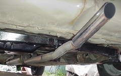
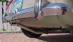
This view shows the tailpipe section. The original system didn't
finish angled upward as I've done here. It came straight out the back, curved upward along the indentation in the bottom
of the trunk (visible in this picture) and then it turned again and pointed staight and level, stopping about even with the
face of the rear bumper.
If you choose to add a chrome tip, make sure the opening in the end is not a lip that
rounds backward toward the interior of the pipe. This lip is actually somewhat restrictive and can cause the system
to whistle or hiss under acceleration.
This is the newest change to the exhaust system. After looking at all the factory brochures
and other information while creating this page and offering advice to several others, I decided to have my tailpipe exit in
the correct look and location. The bends are shallower than the original configuration, but that keeps the exhaust flow
from being restricted.
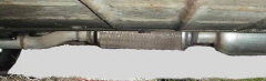
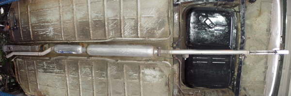
This panoramic shows the exhaust as I now have it. After we
started taking longer trips to British car shows, we realized that one glasspack just wasn't enough to quiet the rumble of
the exhaust tone. It sounded great around town, but after about a half hour on the freeway, it was alittle much.
I decided that with the upper engine stabilizing bar, which has urethane bushings,
I no longer needed the flexible section in the front pipe. I had the exhaust shop install a 3" outer diameter, 2" inner
diameter, 18" long glasspack. We then re-did the rear mounts in softer rubber to allow more flex in the entire system.
This has really quieted the exhaust noise and rumble. The other benefit was that
the increased back pressure from the smaller front glasspack really improved the idle characterists.
The only thing I would change about the system is to have flanges installed on the
glasspacks. They could be replaced easier and without welding, and it would allow me to switch their direction and expirement
with what made the system quieter. Glasspacks have rows of internal louvers. Mounting the glasspack
so that the louvers are facing the exhaust flow quiets the exhaust more, but impedes flow and vise versa.
If you would like larger versions of these pictures please email me.
|