|
Warning! Working on cars takes patience,
knowledge, skill, proper tools, proper safety equipment, common sense, and an understanding of automotive maintenance, repair,
and theory. Working on cars can be dangerous and even lethal. Working on cars can make problems worse,
can cause new problems and can even damage the car. Cars can fall off jacks and kill you. They can crash and kill
you and others when you fail to repair them properly.
My advice on these pages is just that, advice. I am
not trying to re-write the repair manuals, nor am I detailing the "only" way to do something. I am merely showing
what has worked for me.
In following this advice you are doing so at your own risk.
Ignition system:
The America uses a conventional points and condensor ignition system with a vacuum advance
distributor. The system is set up with an external Ballast Resistor to limit the voltage to the positive side of the
ignition coil to around 9 volts. This keeps the ignition points from being burned by too much current flowing through
them. The external Ballast Resistor is in the form of a resistor wire that runs from the ignition key actuated side
of the fuse box (the side nearest to the firewall). This wire has a built-in resistance that drops the voltage to the
coil.
Ignition Distributor:
-The America uses a Lucas model 25D4, vacuum advance distributor. It rotates in a counter-clockwise
direction. The distributors are marked with 2 codes which can be used to identify the date the distributor was manufactured
as well as the advance curve operation.
One of the most common distributors used on the America is coded "41220 A".
A date stamp will appear below the identification code and will be written as the week and year of the distributor's
production, for example: "8/69" would be the 8th week of 1969. The vacuum advance diaphram
is also stamped with a special code to identify it's function. The code on the back side of the diaphram housing
will be stamped "5/11/8" This represents the vacuum in inches of Mercury when the advance starts, the
vacuum in inches of Mercury when the advance stops and the total amount of vacuum advance in distributor degrees. Double
the "distributor degrees" to get crankshaft degrees.
The mechanical and vacuum advance information for this specific distributor is listed
below:
Mechanical Advance:
-
0.0 degrees of advance below 350 distributor rpm = 700 engine rpm.
-
1.5 degrees of advance at 500 distributor rpm = 1,000 engine rpm.
-
9.0 degrees of advance at 1,000 distributor rpm = 2,000 engine rpm.
-
18.0 degrees of advance at 2,500 distributor rpm = 5,000 engine rpm.
Vacuum Advance:
-
Vacuum advance starts at 5 Hg (inches of Mercury) and reaches it's maximum at 11 Hg (inches of Mercury).
-
16 degrees of total vacuum advance is achieved at the crankshaft. (This is 8 distributor degrees.)
-Mechanical advance weights are located just under the backing plate that the points are
mounted on. They need to be lubed occasionally. Simply squirt some spray lubricant or engine oil in behind the
backing plate. Any excess will run out of the body of the distributor through a drain hole.
-Check that the vacuum advance is working as part of your general tune-up proceedures. To
check, remove the vacuum line that is attached to the end of the diaphram. Remove the distributor cap. Now
push upward on the pin that attaches the vacuum advance rod to the points backing plate. This is in the 8 O'clock
position roughly. Hold the pin in the upward position and then put your finger over the hole where the vacuum
line attached. Press your finger down hard enough to make a good seal on the opening. Let go of
the pin. It should stay where you pushed it. If it drops, you have a torn diaphram in the vacuum advance
unit. It is not repairable and must be replaced.
Vacuum Advance Rebuilder:
November 2012: I've just received some great information about a company in the USA
that rebuilds vacuum advance units for British cars.
British Vacuum Unit
Canterbury, NH
Phone: (603)783-0566
Email: britishvacuumunit (at) isp (dot) com
Plug Wires:
-Bad plug wires can cause numerous starting and running problems including poor
cold starting, mis-firing at idle and cruise, and stumbling under hard acceleration, to name just a few.
-Make sure you have a quality set of plug wires and that they have a resistance of 6,000-9,000 ohms.
You can make a nice set using bulk Beldon Steel Core plug wire material available at auto supply sources like NAPA, etc.
Steel Core plug wire has virtually zero resistance, so you'll need to install resistor type plug wire ends. These are
also available from many automotive sources. As mentioned look for ends with 6,000-9,000 ohms of resistance. The
ends will sometimes be stamped with their resistance value. Something like "9k" to represent
9,000 ohms of resistance. I'm using some vintage looking ends that say "Champion" and are 10,000 ohms. They have
been working excellent and look really nice too.
| Bosch W7DTC Spark plug |
|
|
| After 250 mile drive. Engine tuned to about 1.5% C.O. at 3,500rpm. |
Spark Plugs:
-Buy a quality set of spark plugs and stay away from the fancy plugs including Bosch Platinums, Split-fire,
etc. as they will eventually lead to some sort of drive-ability problem.
-NGK BP6ES seem to be the most highly recommended and gap them to .028".
-Due to my experience with Bosch products, I've been using both the "Bosch Super" which is their
standard plug in a W 7DC heat range. That is their correct plug for the A-series engine.
-If you want to run a very stable and wear free plug try the Bosch W 7DTC. This is a triple
electrode plug that was developed for a more stable idle in the VW Jettas. I've seen them with 60,000 miles and still
going strong! I've been running them for about 2 years now with great success. They do not need to be gapped.
-Always put some anti-seize compound, or at least some engine oil from the dip stick, onto the spark
plug threads before installing them.
Ignition Coil:
-Since the America uses an external Ballast Resistor, (in the form of a resistor wire coming from the fuse box to the
positive side of the coil) you need a coil that uses an external ballast resistor too. The Lucas Sport Coil and Bosch
Blue Coil are both 3 ohm resistance coils and therefore do not need an external ballast resistor. So, if you want
to upgrade to one of these better coils, and I highly recommend that you do, they need to be powered by a different wire from
the ignition key side of the fuse box. If you power them with the original resistor wire to the positive side of the
coil, you're defeating the purpose of installing them.
-Alternatively, you can upgrade to electronic ignition with the Pertronix Ignitor and matching Flame Thrower Coil
for about $109 including shipping from Carl at "Retro Rockets." (See the "Parts Source" page for his details.) The Ignitor
fits completely inside the distributor and replaces the points and condensor that are mounted there. It takes
about :15min. to install. It will be the best money you spend on your engine! I installed one last year and am
very impressed. There is a very noticeable difference in performance and power. Even the fuel economy is up.
There is a link to a place that has the best prices on them and free shipping on my "Links" page. Like the coils mentioned
above, the Flame Thrower Coil and Ignitor both need a full 12 volts to operate properly.
- The LU-142A Ignitor fits the Austin America distributor.
- The 40511 is the black 3.0 ohm coil and is what I use. Using that coil, you can run 12 volts from an ignition
key source right to the "+" on the coil, then the red and black wires of the Ignitor go right onto the coil.
Make sure your car is Negative ground and make sure that your current coil's power wire is providing a full 12 volts to
the coil, and doesn't have a resistor block, or a resistor wire in it somewhere to lower the supply voltage. The 1970
cars have a resistor wire feeding their stock coil. So you can't use that to power your Pertronix 3.0 ohm coil.
As
I stated above, I like to run the Bosch W7DTC 3 electrode plugs with this system. Whatever plug you choose to run,
bring the gap out to .035-.040".
Solving a Misfire:
-Due to the lengthy content, I've dedicated a whole page to this issue. Click on the link
below to jump to that page now.
Solving Driveability Issues
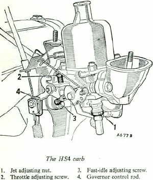
Fuel & Exhaust System:
| S.U. Carburetor |
|
|
| The single 1-1/2" HS-4 |
An internal combustion engine is basically
an air pump, so what goes in has to come out. The more flow, the more power.
Carburetor:
The America's originally came with a single HS4, 1-1/2" diameter SU carburetor. This is a
great carburetor and it has plenty of potential. It is also simple and easy to work on and parts are very inexpensive.
The
1275 A series engine fitted in the America can handle twin 1-1/4" SU's, a single 1-3/4" SU and even twin 1-1/2" SU's if built
right. I've stayed with the original carburetor because it does what I need and retains the original look.
If you
want to get the most out of the stock carburetor, here are some things you can do.
-Install a K&N air filter and
then re-adjust the mixture setting. This filter allows the carb to take in an increased amount of air will tend to lean the
fuel mixture somewhat.
-Use ATF (automatic transmission fluid) in your dashpot (or a similarly thin 5w or 10w oil).
This will increase the carb's ability to respond to acceleration, without causing a lag. I've been using ATF since I put the
car on the road.
-Make sure the float level is set to 1/8". This is very important. An incorrect float level really
affects carburetor and engine performance adversely!
-Replace the throttle plate that has a "pop-valve" in it, with
a "solid" throttle plate without a valve. The "pop-valves" can leak intermittently and cause a poor, unstable idle. Plus,
they hang down and obstruct the airflow into the engine.
-Make sure you have the correct piston return spring and
that it is in good shape and is the correct length. The correct spring for the America is the "Red" color coded spring. Replace
yours if you're not sure. If yours isn't correct, the carb and engine performance will suffer. They're very inexpensive.
-Make
sure your needle and jet tube are not worn. They are inexpensive and easy to replace. If worn, they cause high fuel consumption
and poor idle characteristics.
-Make sure your throttle shaft isn't worn by trying to wiggle the shaft up and down,
and front to back. If you have excessive play here, it will cause an air leak, resulting in poor idle characteristics. Oversized
shafts are available, but you'll probably want the local British car shop to do this repair unless you have the tools and
skill.
| Modified air intake |
|
|
| 2" diameter mandrel bent tubing |
Air Intake Modification:
The stock air intake tube is actually a smaller diameter than the intake opening of the carburetor.
This is quite a restriction to incoming airflow. You can modify the air intake tube very inexpensively and get some
great results.
-You can use 2" diameter, thin wall, mandrel bent exhaust tubing and it works excellent.
Looks stock, moves alot of air and I think it decreases the intake noise.
Buy a "U" shaped section of premade tubing from your local exhaust shop for about $10-$15.
Select a "U" shape that has a bend radius of just over 8 inches. Cut a "J"
shape out of the "U". Cut one of the left over straight pieces so that it is about the same length
as the tube that comes out of the air cleaner housing. This will roughly be about 3" long. Expand about
2-1/2" of that section, so the curved end of your "J" will slip inside. The other end of that
straight will fit into the stock air cleaner housing if you enlarge the air cleaner's opening a bit. You'll be cutting
off the original tube on the aire cleaner housing. The new expanded tube can be MIG welded in place if you have
a metal air cleaner housing or JB Welded (epoxy) in place if you have a plastic air cleaner housing.
Flare the "straight" end of the "J" shaped tube so it looks like the trumpet flare on the stock intake
tube. Your exhuast shop will have a machine that can create this flare. They will also have the exhaust
pipe expander to expand the short straight piece. A coat of primer and semi-gloss paint will finish the job and make
it look just like original.
I've done this modification and noticed a big difference in idle smoothness and power at cruise speeds. The
intake noise seems quieter under hard acceleration and when pulling long hills, the engine will hold it's speed much easier.
I'm very happy with the results.
| Pipe comparison |
|
|
| 1.5" dia. pipe versus 2" dia. pipe |
| Making the pipe |
|
|
| Line up the curvature and mark for cutting |
| Final shape |
|
|
| Flare end after cutting, then paint |
| Finished product |
|
|
| Black powder coated finish |
Exhaust System:
If you want to get the most out of your engine, no matter what kind of horsepower, performance
or economy that you're looking for, then you'll need to do something with the exhaust.
The stock 1275cc engine can
handle both 1-1/2" and 1-3/4" diameter exhaust pipe from the manifold all the way back. If you've rebuilt the engine
and bored the cylinders you definately want to make some exhaust improvements. Either of these sizes will be a tremendous
improvement over the original 1-1/4" pipe, which is extremely restrictive and performance robbing.
- Have your exhaust
work done by a competent independant shop. Stay away from the production chain shops. Their work is terrible, regardless of
their lifetime warrantees!
- Make sure your new exhaust system has 2 mufflers. The first muffler will break up the
sound waves and the second muffler will be able to significantly quite the rumble at cruise speeds. If you opt for just
one muffler, it will sound great, but on the freeway it will be too loud. I ran one 4" diameter, 24" long glass pack
for years. It was great around town and on short hops on the freeway. But after 15 or 20 minutes at freeway speeds,
it was too loud.
- You can fit 2, long, 4" diameter glass packs in the tunnel that runs from the back of the remote
shifter housing to the rear subframe. It will still sound nice, but will be much quieter on the freeway. I now have
an 18" glass pack in front of my 24" glass pack. Adding another glass pack made a big difference in the noise on the
freeway, yet only quieted it somewhat around town. I'm very pleased with the change and highly recommend this configuration.
- Make sure the exhaust is hung on soft rubber mounts. It needs to move, so let it.
If you don't, you'll continue to break the connection at the manifold. So, make sure the mounts are soft and flexible (whether
you use the factory mounts, or the soft rubber ones available at the muffler shop). The muffler shops also carry a mount
material that looks like a section cut from a car tire. These are too rigid so try to use something softer.
-
If you want to keep the stock manifold, you can easily modify it to flow better. Just enlarge the intake and exhaust
openings as far as you can reach with a die-grinder. You can also cut off the flared "bell" connection end that the down pipe
attaches to and have the muffler shop weld a 2-bolt flange in place. That way you'll have a nice bolted and gasketed connection
to your exhaust pipe. I have also done this after fighting the original bell connection that always leaked and made
noise. Plus, with the 2 bolt flange connection you can start your 1-1/2" or 1-3/4" exhaust from that point.
No more need for a down pipe that has some sort of step-up connection from the old original diameter pipe to your new system.
In my opinion, if you use the original manifold, this is the best way to go.
-For more detailed information and pictures, please take a look at the
"Exhaust System" page.
Electric Fuel Pump:
-If you want to convert your electric fuel pump over to a transistorized set up, it's easy, inexpensive and dependable. I
have not done this, but many have with great success. Click on the link for the type of electric system you have.
Negative Ground System
Positive Ground System
Fuel Pump Fault Diagnosis:
-First of all, disconnect the fuel supply hose at the carburetor
float bowl. Place it into a small container and turn on the ignition. You should have a nice stead flow of fuel
and you should hear the fuel plump clicking away repeatedly in the trunk.
If you don't have fuel flow and a clicking pump, tap the pump on it's end with the handle of a screwdriver.
If the pump begins clicking, and if you have fuel flow out at the carb, then you know the "system" is probably okay, and the
pump's points just need cleaned. Remove the end cap of the pump and sand a clean surface on the points using wet/dry
paper folded do it's double-sided and some WD-40, Liquid Wrench, PB Blaster, or Kroil as your cutting oil.
If you don't have a clicking pump after smacking it, then check for both good voltage and a good
ground. You should have 12v feeding the pump. The ground wire runs from the side of the pump body (under the car)
out to a mounting stud/nut on the trunk wall around the pump mounting area. You'll need a digital volt/ohm meter to
do this test. If you don't have on, they are reasonably priced at Sears and Harbor Freight, to name a few. Get
one!
Once you have 12 volts feeding the pump, and a good ground connection, and clean contact points,
you should have a working pump. If you don't, the pump is probably bad internally, and it should just be replaced.
You don't want a $75 fuel pump causing a $300 tow truck ride, not to mention being stranded somewhere.
If you get the pump working, but still have no fuel flow to the carb, make sure you don't have a
blocked fuel supply line going from the pump, under the body and up to the carb. You should be able to blow through
this line with your mouth. If you can't, it's plugged. Compressed air may clear it, or you may have to "rod" it
out with some stiff wire or a 10' length of weed eater line put into a drill.
If you get the blockage cleared (if you had a blockage) and still don't have any fuel flow, proceed
as outlined below.
-There are several faults that will cause the pumps to click repeatedly,
or flutter, ultimately starving the engine for fuel. This can be a constant problem, or an intermittent problem.
1) Faults ahead of the pump, including pickup pipe
screen, pickup pipe, and incoming fuel hose, will all cause this...both individually and together.
2) Problems with the reed valves in the pump, a
tear in the diaphram, or failing points assembly will also cause this.
3) Leaks in the fuel system after the pump, including
the supply pipe and the hose to the carbs, and the carb float needle, will also cause your symptoms.
Testing the fuel pump:
First of all remember that you are working with gasoline and gasoline
vapors. So, don't blow yourself up or set fire to yourself, your car or your home. Work safe and if you don't
feel comfortable with this, take the car to a competent shop.
The fastest easiest way to diagnos is to remove the pump from the
car. Hook it up to a 12v power source and allow it to draw fuel out of a container and pump into a seperate container. You
can actually have it pump back into the same container to recirculate the fuel, which is the way I usually do it.
If you put your finger over the fuel outlet, the pump should stop
ticking. Generally the pump will not completely stop ticking. But, it will only tick once every 10 or 15 seconds,
or so. If you then move your finger slightly to allow some fuel to escape at an even rate, the pump should tick every second
or so.
If you get fluttering of the points, or double clicks, etc. I would
recommend simply replacing the pump, as they are fairly inexpensive. You can play around with disassembling and cleaning
the reed valves, cleaning/adjusting the points, and even replacing the diaphram but you may find it a false economy.
Although it is fun to work on them. (I did take my pump completely apart, cleaned and adjusted everything and put it
back together according to the factory BMC manual. It worked fine for about one year, and then acted up again.
At that time, I simply replaced it. It was the original pump, now 32 years old, so I think I'd gotten my monies-worth
out of it.
On the other hand, if the pump works fine out of the car, then you
know the fault lies in the car. Pretty easy to find the "in-car" fault after this test. Just repeat the above
test with the pump back in the car.
1) Let the pump draw from the car's fuel tank
and pump into a container, using your finger to control the flow. Repeated clicking will mean a problem in the fuel feed
pipe, or the fuel hose coming from the fuel tank. Probably due to some sort of a pin hole, or possibly the pick-up
pipe's screen is plugged with rust.
2) Let the pump draw from a container while hooked
up to the hose feeding the carb. With the engine off, the pump should click repeatedly until it pressurizes the fuel
line, then stop clicking. It should then click about every 15 seconds or so. If it double clicks or continues
to click repeatedly, check for leaks in the hose from the fuel pump to the pipe in the body, and in the pipe that runs under
the body, and in the hose that runs up the firewall to the carb. If there are no leaks here, then pull the dome and
piston off the carb and see if fuel is running into the engine indicating a bad carb float needle and seat. Usually
a bad needle and seat will cause the carb bowl to drip fuel out onto the exhaust manifold....always an exciting sight, especially
on a hot manifold!
Fuel Tank:
If your gas tank is leaking, it can be repaired easily and inexpensively.
Although most radiator repair shops also repair gas tanks, you can do a great job yourself.
-Typically, the gas tanks
rust-out from the inside and usually right in the area of the drain bolt. In this area the gas tank is deeper and this is
where the water collects. Since water is heavier than gasoline, the water sits at the bottom of the tank and eventually rusts
it out. There are a number of products on the market that are fuel proof and can be applied to the outside of the tank if
you get in a pinch and need to fix the leak temporarily. They will work for awhile. I had a nice patch of JB Weld epoxy on
mine for a few years and it worked pretty good.
However, patching the outside doesn't stop the rust process on the
inside. So, the only real permanent fix is to remove the tank and coat it on the inside with aviation fuel tank re-liner.
The product I used is called "Red Kote". It is a liquid vinyl type compond. You steam clean the tank inside as best you can,
knock and blow out all rust and other crud that is loose. Then pour in a pint of the Red Kote, and slowly slosh it around
so it coats the whole inside. Pour out the excess and let it dry. It is fuel proof and will never fail. All rust and other
particles will be permanently sealed in place.
The only word of caution is that you have to make sure that the product
doesn't close off the vent tubes and the pick-up tube screen. Also,there is baffle plate that keeps fuel from running away
from the pick-up tube when you go around corners. This baffle plate is only tack welded to the bottom of the tank so it does
allow fuel to move back and forth as the fuel level drops. When I did mine, the product sealed the bottom of the baffle and
that caused the baffle to keep 3/4 of the fuel from reaching the pick-up. So, I had a car that ran out of gas after 3 gallons.
There is no way to remove the product once it's cured, so I had to modify my baffle to allow it to pass fuel again.
Other
than that, this product is absolutely the best. I have used it successfully several times.
Fuel Gauge Malfunctions & Repairs:
If your gas gauge is either not working properly, there can be several causes.
The sender in the fuel tank could be bad, the wiring to the gauge could be bad, or the
gauge could be receiving the wrong amount of voltage.
As always, start with the simple and work toward the complex.
In the trunk next to the electric fuel pump, you'll find a green wire with a black stripe
coming from the lower right fender below the tail light assembly. It will plug into a black rubber connector, then disappear
through the wall of the trunk where it goes across the top of the fuel tank to the sender.
Disconnect the wire that comes from the right fender area and touch the male end to the
silver screw that is just to the 2 O'clock position of the fuel pump. With the ignition key "on" the fuel gauge needle
should be pointing to the "F".
If it does, you know the wiring is fine and the gauge is fine and that your problem lies
either in the short wire leading to the sender, or in the sender itself.
If it does not point to the "F" then you either have bad wiring to the gauge, a bad gauge,
or no voltage going to the gauge. Time to break out the voltage meter and start doing some other tests. The green
wire should run all the way to the gauge. The gauge should be receiving about 9 or 10 volts from the voltage stabilizer
on the back of the speedometer. If it's getting too much voltage, replace the stabilizer, if it's not getting any, continue testing
and find out why.
If you have a working gauge, and the problem lies in the sender, or the short wire,
you'll need to remove the fuel tank. This is no fun.
Warning! Working on the
fuel system, especially with the fuel tank, can kill you or injur you and anyone around you. Fuel explodes, fuel vapors
explode, fuel vapors in your garage can be ignited by the pilot light and burner of your gas water heater or gas furnase,
or gas clothes dryer! Fuel will burn your skin, damage and possibly blind your eyes and can kill you if swallowed.
Fuel vapors are toxic to breath and can make you loose consciousness. THINK BEFORE WORKING ON YOUR FUEL SYSTEM!!!
- Jack up the rear of the car and put it on stands. Chock the front wheels.
- Drain the fuel. The tanks can hold up to 10 gallons. Be prepared to catch that
much fuel. There is a bolt in the bottom of the tank. Please wear safety goggles, and gloves and don't wear long
sleaves because they can really trap the fuel against your skin and burn you badly. Better to have some fuel on your
bare skin and wash it right off, then to soak your shirt or jacket sleeve and have it held against your skin and breath the
fumes!
- While underneath, spray all the bolts that hold the tank to the car, with "Liquid Wrench"
or "P.B. Blaster" to start loosening the rust and crud on them.
- Remove the vent hoses and fuel filler hose inside the trunk.
- Push the green and black wire through the trunk wall and remove the rubber grommet.
- Underneath, remove the pipe fitting in the left side of the tank.
- Remove the little screw and nut that hold the other metal fuel line on the right side
of the tank.
- You do not need to disconnect the fuel pump hoses from the fuel pipes!
- Remove the exhaust mounts and let the system hang from the front trans mount. That
should give you enough room. If your system is very rusty and old, it will probably break during this. Time for
a new exhaust system anyway.
- Slowly loosen each of the bolts that hold the tank to the car body. These go up into
a sheetmetal flange that has a square captive nut at each location. These are so easy to strip out of their captive
locations!! If you do break the captive nuts loose, you are in for quite a battle. Take your time!! Turn
them a tiny bit in the tightening direction first, then a tiny bit in the loosening direction. Rock them gently back
and forth like this and use your smallest ratchet so you don't have enough leverage to do any damage to the captive nut location.
You'll spend about an hour per broken captive nut, so slow down and take advantage of the "Liquid Wrench" or "PB Blaster."
- Lower the tank and slide it toward the rear.
- Remove the green wire from the sensor. You may want to do a test on the green wire
to make sure it's good, as it could be the sole problem.
- Prepare to remove the fuel level sender by first marking it's location, as well as the
retaining ring on top of it. Scribe some lines on it and on the fuel tank, so you can properly "Clock" it during reassembly.
- Using a large screwdriver and a hammer, knock the retaining ring loose and remove it.
- Now gently pick the sender plate with a screw driver all the way around to carefully loosen
it from the gasket underneath. If you can save this gasket you'll be much better off!
- Rock the sender plate and slowly pull it up and out. You'll have to angle and twist
it to "feed" the float arm and float out of the tank.
- Now that it's out, check to see if the float is full of fuel as in the photo below.
The leak, fill up with fuel and then sink. This gives you a low or empty reading all the time.
- If the float has fuel inside, take a needle and poke a hole in each end. Blow the
fuel out. Heat up a screwdriver blade and carefully melt your holes closed so you can reuse the float. Or, you
may find new ones are available. I think they are the same as the Sprite/Midget ones.
- Check that the float arm swings freely. They can get gummed or rusted up an actually
stick in one location.
- Next you'll want to take the sender assembly apart so you can examine the rheostat inside,
and the foot that rides on it, as well as the bronze bushing that the float arm pivots on.
- Bend the 3 tabs up that hold the assembly cover in place and gently lift it away.
The float arm will stay with it and you'll have to rock the float arm to get it disengaged.
- Once inside, you'll see the rheostat windings. Clean them gently with some fine wet/dry
paper. (they may not need it so don't risk damaging them). Clean the foot that runs on them. Clean the bronze
bushing and the area on the assembly housing that it pivots in.
- The other failure that I've seen was in the metal strap that electrically connects
the rheostat to the spade connector at that top of the sender. Notice the spade is sitting in a nylon bushing?
Where the metal strap underneath hits the bottom of this bushing, the strap becomes very thin, more like a wire. It
can break inside the bushing. You can carve the bushing away and solder the broken link successfully.
- Press it back together by hand only and test to see if it pivots smoothly. You can
take to to the trunk of the car, touch the body of it to that silver grounding screw near the fuel pump, then hook the green
wire up to it and turn the key "on." Moving the float arm should get a corresponding
reading on the gauge.
- If it works fine, bend the 3 tabs back down, put the float back on the arm and put
it back in the fuel tank. Line up your scribe marks and tap the retaining ring back in position. Put the short
green wire back on
- Remember when you lift the tank up under the car, feed the short green wire through the
trunk wall. You'll be real unhappy if you don't do it at this stage of the game!!
- Put the tank back in, but put some anti-seize compound on the tank bolts before threading
them in.
- Once everything's back together you should have a working gauge.
| Fuel inside float |

|
| You can see the amber colored fuel inside |
| Rheostat |

|
| Make sure this is intact Note connection in nylon bushing above |
| Float arm bushing and foot |

|
| Note the goop on the bushing that had glued the float arm in place |
Fuel smell inside car:
Fuel smell problem?
On my 1970 model with California emission's system and fuel
tank vapor recovery, I used to get an odor. It would be right after I filled up. Otherwise it was fine. I finally
found my odor came from the cracks in the rubber hose that connected the fuel fill pipe to the top of the tank. I
replaced this rubber connection with some generic fuel rated stuff that I found at NAPA. Problem completely solved.
I also used to get fumes from the 2 vent pipes that stick up
through the trunk near the rear seat and have rubber 90 degree elbows that connect them to the metal vent pipe. The elbows
failed years ago because the trunk shelf can smash them when it gets displaced. I replaced them with some clear PVC
hose that was soft enough to bend and not kink. This was a temporary fix that's now lasted about 10 years. I think lengths
of PVC don't make the tightest seal on the tank nipples, but I keep forgetting to replace them.
So, check for a weeping fuel tank seem, or leaking from the
bottom of the tank where it is likely to be rusted out. Check that the seal at the fuel level sender opening
isn't leaking. Also, check the condition of your vent system. It might not be sealed tight or might not be
working for some other reason.
1968 & 1969 Year Models:
(And 1970-1971 with Non-Vapor recovery emissions control
systems)
Make sure that the vent hose in the trunk is in good condition and is properly
attached. It simply clamps to the vent nipple rising out of the fuel tank. Then it goes straight up under the
parcel shelf where it runs through a holding strap. It then runs back down to the left corner of the trunk just behind
the rear seat back. In this location is is again clamped to a metal nipple. This nipple is part of the trunk floor
and allows the vent tube to vent and even spill fuel right out the bottom of the car. Don't be surprized if when filling
up the tank, the vent pipe dumps fuel on the ground as the tank reaches the full mark.
1970 & 1971 Year Models:
(With Vapor recovery emissions control systems)
Your America may have the same system as mine depending on
where it was first sold. If so, your fuel tank vapors should be going all the way to the charcoal canister mounted on
the firewall and then into the engine via the hose from the canister to the valve cover. Make sure your oil filler cap
is the non-vented style so the engine only draws "fresh" air in through the canister and over the charcaol granules, hence
purging the fuel vapors from the granules.
Check for: A blocked vent
line running from the filler neck all the way up to the charcoal cannister. Mine was blocked in the steel line and I
opened it up using an old speedo cable like a drill bit, then followed with compressed air. Also, check that you can suck
air through the charcoal canister, by sucking on the pipe that goes to the valve cover. There's a removable screen in the
bottom of the canister that you can clean. Just unscrew the bottom of the canister. Also, you can replace the charcoal
inside the canister with aquarium charcaol from the pet store.
Gas Cap:
If you own an America with the larger gas filler neck that uses the larger diameter cap then you may find this helpful:
The larger diameter cap and filler neck appear to have been used from late '69 onward. Although I'm not familiar with
how the cars were set up for other states, here in California, we have them. (Our '68 and '69 cars have the smaller cap which
is still available.)
As far as I can tell, this larger cap is no longer made, although I could be wrong. I left
mine on the roof one day after running out of gas on the freeway, and drove off. I called all over the USA and could not
find one. In fact several places told me if I did find a source to let them know because they had customers who needed one.
Nessecity is truely the mother of invention and this is a prime example!
I went down to my friends at "British
Sports Cars" and started looking at the cars they were working on to see if any of them might use the same cap. Nothing
appeared to be correct and the owner, my good friend Peter Jurgens, didn't think the cap was used on anything else either.
So, I decided to just try to find something close for the time being. The late MG Midget caps were the correct
diameter, but had the wrong tabs to grab the filler neck. So, I asked if they had any Austin Marina caps. They did! The
Marina uses a plain cap without the stainless steel outer grip area because it doesn't show. However, the Marina cap fits
the America's filler neck perfect.
I started looking at the Marina cap and comparing it to the Midget cap. It
appeared the Midget cap was made in two pieces and that the stainless outer grip area was simply machine crimped in place
over the interior part that grabs the filler neck. It looked like I might be able to remove the stainless piece from the
Midget cap and "snap" it on top of the Marina cap.
So, I clamped the Midget cap in a vise, took a die-grinder
cut-off wheel and carefully cut the internals of the Midget cap out. Although I had to be carefull, the job was easy and
went fast. I cut straight accross the middle of the internals of the Midget cap. The cut line released tension from the
stainless cover piece. Then I grabbed the internals with pliers to crush them down a bit smaller and popped the stainless
cover off.
I took the Marina cap and laid it on top of the vise with the jaws open just enough to allow the grip
area of the cap to sit on the jaws, but the internal part was able to hang free. I placed the Midget cap stainless cover
over the top of the Marina cap, centered it, and gave it a very forceful shove downward.
The Midget cap stainless
cover snapped right into place!
Instant Austin America Gas cap!
|