|
Electrical System:
| The heart of the electrical system |
|
|
| And sometimes.....the mind of the car. |
The universal challenge of British car ownership,
the electrical system!
Wiring Diagram with Legend:
-For clarity, I've dedicated an entire page to the display of a large easy to read wiring
diagram and legend. If you need help reading and understanding it, please feel free to email me. I enjoy electronics
and wiring brain teasers.
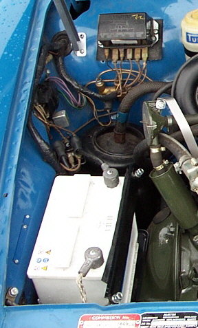
Fuse box:
-As you can see in the factory diagram above, the fuse box is located on the passenger side
(right side) inner fender, just above the starter solenoid.
-The fuse box contains two 35amp fuses and two spare fuses.
-If you have electrical items that aren't working, or were working, but have now stopped, look to
the fuse box first. Since the entire car is controlled by only 4 fuses, this is an important area. The fuses
need to be clean and shiny, as do their connectors. Make sure you can see the metal strip or wire inside them
and that it is in tact and not burned in half. These thin strips or wires can also break away from the metal end
caps, so they look in tact but really aren't. If in doubt, test with your voltage meter, or just replace them.
Sometimes just spinning them in place will make a better connection and things like the horn and interior light, etc. will
start working again.
-However, if the curved metal connectors that hold the fuses look a little scruffy, you can
brighten them up using a little brass bristle brush, the ones that look like a tooth brush. You can do the same thing
to the little male ends along the sides of the fuse box. Just remove each wire one at a time, give the male end a scrub
and put the wire back on. If any of the wire connectors seem a little loose, give them a gentle pinch with a pair of
pliers. They fit nice and snug again and that should solve your problems.
-First to clear up a myth. You don't need a huge battery to make your car start, nor
will a huge battery make your lights and other electric items work better.
The proper size for the battery is a Group 51 or Group 51R (reversed terminals).
Depth: 4-3/4" = 121mm
Height: 7-3/4" = 198mm
Width: 9"
= 228mm
The Group 51
- will place the terminals near the engine, for a positive ground car.
- will place the terminals near the inner fender for a negative ground car.
The Group 51R
- will place the terminals near the inner fender for a positive ground car.
- will place the terminals near the engine for a negative ground car.
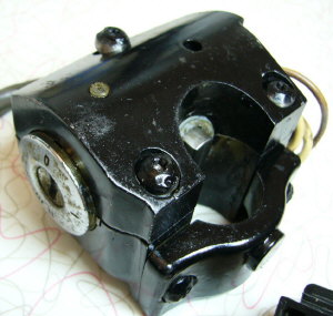
1970 & 1971 Locking ignition:
Repairing
a locking ignition switch:
In the USA, beginning in
1970 the Americas all had locking ignition switches that were mounted to the steering column.
From what I’ve seen, these ignition assemblies are no longer available, and they are at the age that some are
beginning to fail internally. This leaves you with a car that will not activate the starter. The ignition switches can be
taken apart and repaired internally and I hope this info will help you:
Remove both halves of the black plastic shroud on the steering column.
Unplug the electrical connector for the ignition switch (located under the instrument cluster).
Use a small, sharp chisel and hammer to remove the 2 “twist-off” bolts that are in the bottom
of the ignition assembly where it wraps around the steering column.

Remove the ignition switch assembly from the steering column.
Place ignition assembly in a vise and remove the 3 “twist-off” bolts that hold both halves
of the steel housing around the actual ignition switch. You will later replace
all 5 of these “twist-offs” with allen head bolts.
Remove the ignition switch from the steel housing.
Locate a tiny set screw in the side of the ignition switch and remove it.
The screw is in the same side of the ignition switch as the key buzzer switch.
The actual electronic ignition switch (not the key tumbler assembly) will come out the end of switch
assembly if you carefully bend the indentations that hold it in place. You will see these 3 indentations in the pot-metal
housing, equidistant around the brown plastic end of the switch.
Carefully slide the entire electronic switch out. It has
3 springs(2 springs are just plain and 1 spring has a metal pin on the end) inside and as you pull up on the brown
plastic end cap things will sort of come apart. But don’t worry, this all
just presses back together later.
Remove the ignition switch, take it apart and clean out all the old stiff grease and then clean
the brass contact areas both on the brown end cap, and on the brass disk that rotates against the end cap.

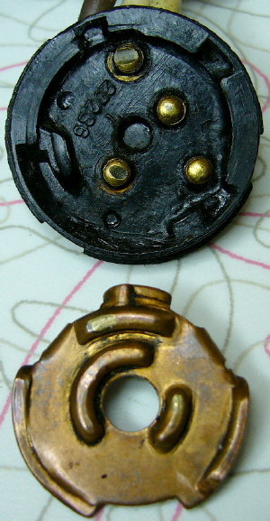
Be sure to inspect the brass contacts for wear or damage and do your best to make them decent again.
Reassemble with some thin grease and reverse the disassembly/removal procedure.
You may need a second pair of hands in order to hold the assembly
in place while you tap the pot-metal indentations back in place.
You can test the switch function using an electric meter on the ohm setting to confirm that you’ve
fixed it.
Re-install in the car using 5 new 5/16"x3/4" long allen bolts in place of the “twist-offs”.
If you don't want to take on this little project, I can repair your switch. I can also have keys
made if you don't have keys for yours, or have extra keys made, as I have a lock smith in town who still carries the blanks.
Email me for a price quote: austinado16 at cs dot com
Generator Diagnostics & Troubleshooting:
Just went through a huge diagnostic on the Generator/charging system on a 1969 America and thought
it might be helpful to post what I learned.
- Generators must spin clockwise to make voltage. They won't make voltage if they are spun counter-clockwise.
- Generators always make some voltage when they are spinning.
- The red Generator light in the dash is an important part of the charging system. The system
will not charge if the light is bad or not hooked up. The ignition powers the light, the Generator grounds it when not
charging. This makes the light stay on.
Here's how the connections on the voltage regulator go and what they mean :
B = Power out
of the regulator to the car and battery
F = Generator Field Winding
WL = Warning Light
D
= Generator (actually D is for Dynamo) output
E = Ground to the body (actually E is for Earth)
So, make sure the wide spade connectors are on the "B" terminals.
Make sure that there is continuity
in the F and D wires. In other words, unplug the D wire from the back of the Generator and unplug it from the voltage
regulator. Now take an Ohm meter and touch the leads to each end of the wire, you should get a small amount of resistance
which shows the wire isn't broken. Now do the same test on the F wire.
If those are both okay, hook them back
up to the Generator. Now leave them off the regulator. Bridge them with a short piece of wire and using a voltage
meter, put the pos. lead of the meter into one of the ends that you've bridged. Touch the black test lead on the meter
to the battery ground. With the engine running at about 1,000rpm+ you should get 18 volts. (This is called "full
fielding the generator")
If you get 18 volts, the Generator is fine and you have a bad regulator. I get
OEM Lucas Regulators for $29 here, so don't pay much more than that.
If you get less than 18 volts, you have a bad
Generator....for whatever reason. They are extremely easy to repair. New brushes and springs are dirt cheap and
take :15min to replace. Polish the commutator with fine sand paper while your're in there.
And finally, I can't
stress enough the need for clean, tight, and large, engine and body grounds. If you want to check them touch the
leads of your Ohm meter to the engine block and to a screw going into the body in the engine compartment somewhere. You
should get nearly zero Ohms. Any other reading shows bad grounds. Do the same test between the battery ground
POST and a screw going into the body on the inner fender. Do the same test between the "E" terminal on the
Voltage Regulator and the body in the engine compartment.
Here's what I found on this car:
- The Generator had a broken brush spring causing the brush to make poor contact with the commutator.
- The "F" wire was partially broken inside the main wiring harness just below the battery. This
caused the "Full Field Test" to only function intermittently. The wire even passed the continuity test described above.....once.
But when tested several days later, it failed.
- The Voltage Regulator had failed. The new Voltage Regulator was bad right
out of the box.
How to convert from positive ground to negative ground:
-Converting from positive to negative ground is very easy. Here are the steps:
1) Disconnect the wires at the generator (dynamo)
2) Swap battery connections around
3) Swap Coil leads
4) Swap Heater leads
5) Re-polarize the generator (dynamo)
Re-polarize the Generator (dynamo):
To re-polarize the generator, connect a jumper wire from the positive side of the battery
and touch it several times to the small terminal on the generator. You will see a small harmless spark. The generator's
magnetic field is now reversed.
Fuel Pump:
Early non-diode containing electric SU fuel pumps are not polarity dependant and
so they don't need the wires switched, a positive 12 volt wire goes to the terminal on the top of the fuel pump, a gounding
wire screws into the base flange of the pump body and then attaches to the wall of the trunk floor. Later replacement
pumps are polarity independant (usually designated by red tape around the top points cover to indicate a positive ground pump,
or black tape to indicate negative ground pump.) The diode inside the top cover of the pump will have to be removed
and re-installed in the reverse direction to change these later pumps over to negative ground.
Heater Blower Motor:
Swapping heater blower motor leads restores the blower to the correct spin direction.
Wiper Motor:
The wiper motor is also polarity independant. No wire changes are required. However,
I have read that the thrust is apparently affected and it has been suggested that the armature housing cover be rotated
180 degrees from it's original position. This can be done by removing the 2 long screws that hold the cover in place.
Convert from positive to negative ground.
Switching from a generator to an alternator:
This tip was sent by Paul Kile via the MG1100 mailing list on Michael Carnell's MG 1100 web site.
"There is an even easier method [of switching from a generator to an alternator] from British Wiring in Illinois(708-481-9050).
They have adaptor harnesses that have the standard Lucas plug on one end and connectors that go to the control box on the
other end. No soldering or bridging of terminals is required. The harness is black braided and looks stock. There are different
ones depending on your car (different lengths), mine was $32.00."
Thanks Paul, great tip!
Add/Convert to a Bosch Alternator:
Hi!
Today i got fed up with lucas wonder regulator and especially reading through that pdf file
about lucas system(the one i post to you as a link)and switched to alternator!
I would like to post out what i have
been through.
i have VW Jetta mk2 at my place,and it has sacrefised its alternator(bosch).It would fit without any modifications,you
even use the original Morris bracket to tighten the belt.Just put that bracket to the other hole in the engine mount(lower
hole,i have 2 holes there,one was upper,where the original bracket was fastened and lower,i used lower hole as it allowed
to use shorter belt)
Just need a little longer belt then original,Jetta belt was too long and you need the belt about circ.920mm
aprox.I have found it in my barn and dont know where it belonged before.
Then wiring:
1)convert to negative ground
2)voltage
regulator might be retained as the junction box,just solder D and B contacts together on the back side or even solder the
D wire on to B wire(single one that goes to solenoid)
2)connect the other end of the original D wire (the one you
have disconnected from your generator)to the positive outlet on the alternator
3)connect F wire (the one from the generator)
to the smaller contact on the alternator
4)you can also connect some thicker wire to the same positive outlet of the alternator
where you connected the D wire and put it right on the solenoid(on the same side that goes to the positive battery contact),that
will give better charging contact
Now hook up everithing to the voltage regulator:
1)D wire/positive from alternator
to D terminal if you have soldered the terminals together,otherwise solder it together with single B wire
2)wire from solenoid(one
of the B wires,single wire)back to B terminal(that wire you have connected to D wire previously by soldering terminals or
wires together)
3)double B wire to the ignition switch back to B terminal
4)thinner wire from alternator that you have
connected to the F wire does not get connected to the regulator,instead you just connect it to the Warning light wire and
insulate connection and leave them alone
5)E wire from voltage regulator stays disconnected as you dont want to ground
the regulator any longer
Or just:
Connect all the wires from the regulator except F ,E and WL together.
Connect
F and WL wires together
Leave E disconnected
What you’ve accomplished is this:
a) the thin wire from
alternator and WL now feed the ignition warning light.
b) the remaining ones from B and D all connect together take the
output from the alternator and feed it to the headlight and ignition switches and to the solenoid/battery.
Everithing
works just fine and i have a nice charge now,all the electrics onboard work better too since the alternator has more power
and allot more stabile current.
I think that you already know how to do that,but anyway i thought that it might help somehow.
With
best regards,Vadim
Thanks Vadim!!
|