Bob's Lost In Space B9 Robot Project | home
Misc. Parts | Motor Shaft Extensions | Knees & Hinges | Treadsections | Tread Making | TreadMaking from Tires | Drive Parts | Drive & Tread Installation | Tread movie | Barry's Tread Movies | Drive Upgrade | Legs | Donut & Waist plate | First Stackup | Torso | Neon | Arms | Microphone & Knob | Chest Buttons | Power Pack | Torso Vents Misc | Making Vents | Large Vent Drawings | Arm Mechanism #1 | B9 Arm Mech Dev. | Wrists & Claws | Collar | Radar | Motorizing Ears | Making Sensors | Brain | Brain Cup & Light Rods | Bulbs & Wiring Diagrams | My Old Robots | B9 Builder's & Info Sites | Related Links | Building Reference Info | Parts Drawing Links | Site Revisions | Final Leg Assembly | Leg & Hip Assembly | Leg-Hip Action | Non-B9 Projects | 2008 TX BUILD-OFF | 2008 TX BUILD-OFF PAGE 2 | RoboCon 2009
Making Torso Vents
Be Patient while this page loads, lots of graphics & photos.
My torso is a copy made from the original (known as the older Fred, Dewey or Rod versions). All nice torsos, the Dewey torso is what the Dave Painter drawings were made from. You can also see reference dimensions from the Dewey torso on Mark T's B9 Robot Resources website.
IMPORTANT NOTE:
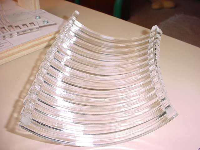
If you have a B9 Creations torso which is a retooled version of the Dewey torso, you may wish to modify my vent patterns to exactly match the torso curvature, height and width of openings. See the following pictures provided by an Austrialian club member who has one of these torsos. (Thanks Glenn for providing the pictures and info!)


The left pic is of a rib made from my pattern placed against the B9 Creations torso and the right pic is a modified rib to fit the compound curvature of the B9 creations torso.
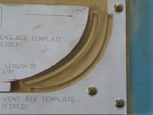
The left rib in this pic is the modified one to fit the B9 Creations torso and the right rib is from my original rib pattern in the drawings to follow.
Material-Get plenty, it's cheap, shipping is not.
To make a set of vents requires only 6 - 6' lengths of 1/4" sq plastic from McMaster Carr - item number 8728K13 - was 1.05 each + shipping (Now 1.39 each 2005). I bought 20 pcs to make the collar & vents last year-2001- for $30 including shipping (2002 I paid $37 for the same amount-shipping went up, plastic was same). You might as well buy plenty extra, because the shipping on this is going to be around $10-15 regardless of how much you get, 1 piece or 20 pieces, as it comes in a large heavy cardboard tube a little over six feet long. Use the extra to make your collar or Holiday decorations.
Then you'll need the paper templates, some wood scraps to make the jigs and a fair amount of patience to cut everything out and put it together.
Click on the link above to download a pdf file of the vent drawings.
I just ask that you do not "sell" these as part of robot plans or books. I created these from scratch for myself and for the "scratch builders" out there, and would ask that they be shared freely at no charge.
You can also go to the next page Large Vent Drawings, where they are shown closer to approx full scale so they are easier to read.


Use spray adhesive to glue copies of the patterns to the wood.

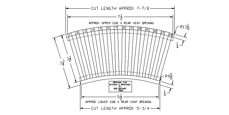
Here's the pattern for the rib template. Material is 1/4" thick MDF (medium density fiberboard) I used my jigsaw to cut it out. (FYI, I only paid $65 for this old upright jigsaw on a stand, it was a good find.)

I use a simple fence jig clamped to my bandsaw to cut the ribs all the same length: 5-3/8" The front vent has 8 ribs and each of the 3 side and rear vents have 14 ribs. That's 50 total.

Ribs
I mounted the fixed portion of the template to a scrap of wood and added a piece of wood for a handle on the slider portion of the template. Put pieces in toaster oven at 200 deg for 3 minutes like the collar pieces, although these are much easier to form.

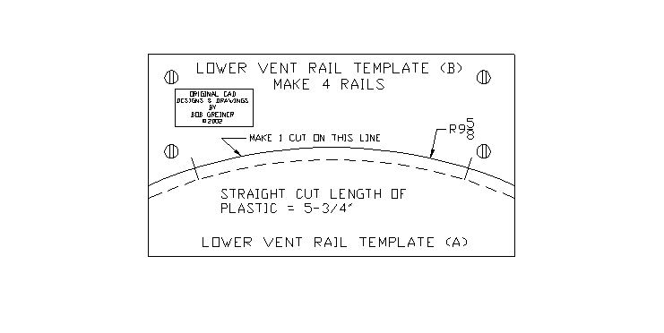
Upper & Lower Vent Horizontal Rails
The template jigs are made the same for these. Material is 1/4" thick MDF. I mounted the top half of these to a board. Actually you wouldn't have to if you use them on a flat surface.

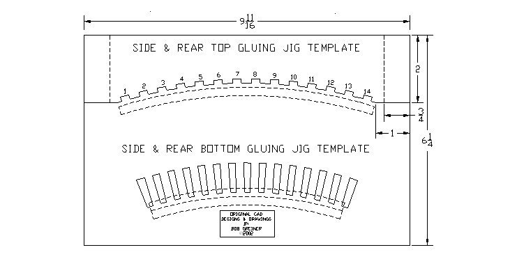
Cutting out the assembly jig for the side and rear vents on the bandsaw. Material is 1/4" thick MDF. You could do this with a handheld jigsaw if you don't have a bandsaw, although a little more patience is required that way.
You will also note that the slots are only 1/8" deep. That is so the jig won't come in contact with the glue when you glue the rails on. And you don't want to captivate the vent with the jig too much or you'll never get it out of the jig after it's glued together.

I just made several cuts straight in to saw away the material.
Use a scrap of the 1/4" plastic rod to check for fit.

Using a second copy of the base layout pattern, I cut out a jig to hold the bottom of the rods from 1/8" thick masonite (hardboard). You don't want it any thicker because it needs to be low enough to avoid coming in contact with the glue when you put the rail on, and you don't want the pieces to become too captive or you won't get the vent out of the jig after you've glued it together.

Again I just used several straight cuts to remove the unwanted material.

Be sure to check them for a just fit with a scrap of rod as you cut them. You can't have them too tight or you will have assembly problems. They need to just set in place.

Well here it is with all the pieces assembled. For the base, I've shown 1/2" thick on the drawings, but 1/2 or 3/4 is fine.

The rest is fairly easy. Put all the pieces in place, then put a fairly generous dab of GOOP household adhesive on top of the end of each rib and gently press the rail into place and hold for a minute or so. Do not apply great amounts of pressure, you don't want all the goop to squeeze out of the joint. See the next pictures below.

GOOP dabs applied to each rib.
NOTE-I have purposely made the height of the jig 1/8" shorter than the ribs when they are in place, just in case you want to level off the tops of the ribs and place your horizontal rail on top of them as the alternate mounting position I show on the rib drawing. This gives clearance so you don't glue it to the jig if you choose to do it this way.

This is how it should look with the horizontal rail in place on the GOOP. DO NOT PRESS DOWN HARD-USE ONLY ENOUGH PRESSURE TO JUST EVENLY SPREAD THE GOOP WHICH WILL FILL THE JOINT.
Don't worry if it isn't perfect, I did a few to work out my technique and you get better as you go along. These joints are not really going to show once in the robot anyway.

This shows the glued position of the bottom horizontal rail. I chose this method because it is easier to glue and a less accurate fit is needed than making an end joint to all the ribs. Then just glue the top horizontal rail on the same way. Hold it for a minute or so until the goop begins to set and then just leave the whole thing set for 4 to 5 hours before you attempt to remove it from the jig.
(The dotted lines show the alternate rail mounting position. If you did it that way, you would need to put a piece of waxed paper on the jig to prevent gluing the vent to the jig.)
When removing it from the jig, just start at the top and gently work it loose from behind each of the rails. This pic shows those rail positions I chose for easy assembly.

Another view.

Here it is just setting in my torso with a little tape. This is the back vent opening which is a little wider than the others on my torso (which is suppose to be a clone of the original).

Another view showing fit of vent to rear opening.

Here it is in one of the side openings. Note that my two side openings are not exactly the same either on my "original" torso. The robot wasn't a refined design by any means (after all it was a studio prop-an expensive one at that).

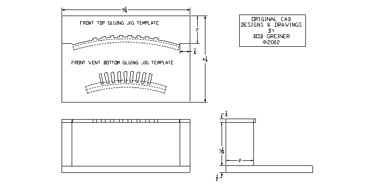
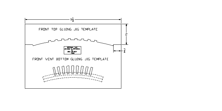
Same type of jig for the front vent, just different dimensions.

Another view showing horizontal rails glued in place to the ribs. Note, I used the same rail dimensions for the front vent as for the side and rear vents.

Here it is removed from the jig. You can cut off the excess rail length if you want to, or cut them before you glue them on. I'll probably leave them long for the channel slides. Also if you leave them long you can set it in the torso vent opening and it won't fall out.

Here it is just setting in the torso. When mounted with the slide channels, it will actually be up a little higher than in this photo, which will place the bottom of the rails level with the bottom inside of the torso.
More to come.
I will be working on a fairly simple way to bend the aluminum channel slides to make an even radius (one way is to use a wood jig cut to a slightly smaller radius than you need and will fit into the channel, then gently roll it into shape around the jig-in progressive steps). I may mount all my vents so they can slide to open for easy access to the inside, rather than just the front vent.
Go to Arm Mechanism #1