Dave's Yamaha XJ Page | home
Tuning your XJ | XJ Electrical diagrams. | Ignition Problems
Ignition Problems

For many years my Police Special had a very nasty habit of dying like I had hit the kill switch.
It never sputtered first and would almost always do it within the first 1 km from my home.
Most times after cranking for a couple of minutes it would suddenly start and carry on like nothing had ever happened. <Grrrr!>
Now this sort of behavior from my bike just doesn't sit right for long so I started taking tests on the electric's and fuel system.
I was never able to fault the fuel system and the intermittent nature of the fault was making tracking electrical faults less than fun.
I checked resistance's of all the electric's against the manual, I did find a few connectors in the loom that had a high resistance in excess of about 5-10 ohm's but cleaning these up never cured it.
For a wiring loom anything over 2 ohms resistance is cause for concern.
Likewise cleaning out all the handle bar and ignition switch contacts did show up some high resistance's, but none were the problem.
Eventually the only things left were the ignition pickup coils and the Transistor Controlled Ignition Module (TCI). The TCI was the one part I had hoped would not be the problem but I was wrong. I swapped modules with another bike and sure enough the symptoms went with it.
This was not a good day, with a second hand unit (if you can find one) costing at least NZD 80 or NZD 600 new, I had to fix this thing! If you don't have experience with a soldering iron it may be best to entrust this job to an electronics technician.
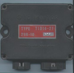

Later type from a 1983 XJ750EII Older type as used on my 1985 XJ750P
(Remember the XJ750P is actually based on the 1981-82 Seca and may have been used as a way to get rid of new old stock parts)
There are a number of different TCI's used on XJ's. Here the later design on the left has been highlighted for part identification and the older design is on the right.
There are two basic types that I have found, In my experience they will interchange BUT they originally came out on bikes with different resistance pickup and ignition coils. If you need to interchange the two types it must be your call.
Within the two basic types there are also variations in the part numbers although they are all of the same basic construction inside even down to the same components used on the PCB'd so I am not sure why they carry different part numbers. It may be that the main IC is programable for different torque curves and timing angles but I have been unable to confirm this as yet.
I have used different numbered boxes of both basic designs in different bikes without any apparent problems.
I opened up the TCI and had a look......


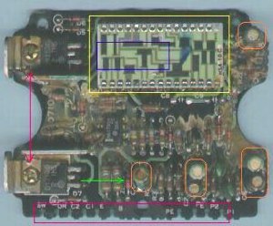
Inside the left hand unit there is a Printed Circuit Board (PCB'd) that is held in by 3 screws and a line of soldered connections down the edge (red box) that connect the board to the sockets where the wiring plugs into the case. The right hand one has the edge solder and two screws through the back of the case.
To remove the PCB'd from the case you must first de-solder the edge connections using a fine tip soldering iron (blunt pencil tip about 40 watts is ideal) and a solder sucker like this....

....or a soldering station with de-soldering capabilities is even better.
To de-solder you must melt the connection with your iron and suck the solder away with the solder sucker thus releasing each connection.
Once the solder is removed and you have removed the screws you may also have to GENTLY prize the PCB'd out of the case.
The next step is to have a close look at the board....

There are a few things to note.
Firstly after adding the components to the board in the factory they have sprayed it with an electrical lacer to seal it against water and then poured a contact adhesive glue over the component side to dampen vibration that can break off the legs of the taller components. Both of these can be removed without damage to the PCB'd by soaking an old toothbrush in acetone and gently scrubbing the PCB'd clean.
Also of note is the ceramic etched PCB (yellow box) mounted up on legs over the top of some other components including the main Integrated Circuit (IC in blue box) and the fact that there are tracks on both sides of the PCB with links passing through with many of the component legs.

The ceramic PCB is very delicate and easily damaged!!
Firstly you need to check for dry joints on the PCB.
What is a dry joint? A dry joint is one thing, TROUBLE! It is a connection with a high electrical resistance and is often not actually connected firmly resulting in intermittent faults.

On the left is a good joint. It is bright and shiny and smooth. On the right is the curse of any circuit, a dry joint, note the obvious ring around the wire, this is in fact a crack in the solder caused by either vibration or electrical loading resulting in heat. You can also make out the satin finish on the solder as apposed to the bright smooth appearance on the good joint on the left.
A dry joint will often show signs of arcing with charring around the connection but this is normally only on components that are passing a high current (amps).
They are easy to fix, simply reflow the solder with your iron and add a small amount of fresh resin cored solder. If it is a really bad joint it is wise to remove all the old solder with your sucker and renew it with fresh solder.
This PCB'd has some very tiny joints that you will need a good light and a magnifying glass to inspect properly. Its often easier just to re-solder every joint.
The most important thing with both de-soldering and re-soldering is to get as much heat into the joint in the shortest possible time. Too little heat and a new joint is more likely to go dry again, where too much heat for too long can damage the components and lift the copper tracks from the board.
Now the bad news, On my TCI there were some dry joints on the main IC under the ceramic PCB'd that could only be got at by removing the ceramic PCB'd from the main PCB'd.
I managed this by heating the solder from the component side of the main PCB'd and sucking the solder through the holes from the track side with the solder sucker. Again, care must be taken to do each joint as fast as you can or too much heat can damage the PCB'd.
Eventually the ceramic PCB'd was out of the way and it was a simple matter to reflow the joints on the main IC and refit the ceramic PCB'd.
There are also six electrolytic capacitors (orange circles) on the board. The sizes of these are
1 off 2.2uf 50 volt
3 off 10uf 63 volt
2 off 0.47uf 50 volt
This type of capacitor is prone to failure from age, heat, and vibration and should also be replaced. They are only a few cents each. Note that they are a polarized component and must be fitted the correct way around so take note of the (-) sign on the side of each capacitor and the (+) signs printed on the PCB'd.
Some of the capacitors have their wire soldered on both sides of the board. They can be difficult to remove without damaging the tracks. Again I was able to suck the solder through the hole to the other side with my solder sucker. I found that by pre-tinning the legs of the new capacitors the solder would flow through the hole and give a good connection on both sides of the PCB'd
Pre-tinning is done by adding solder in a thin layer to the wires of the component before passing them through the PCB'd and finally soldering them down.
There have also been cases I have heard of where the main power transistors (red arrow) mounted to the heat sinks can fail resulting in the loss of ignition to the two cylinders fed by each transistor. I have not as yet run into this problem but I understand there is a replacement available.
Also the 12 volt Zener Diode (green arrow) has been known to fail. This causes total failure of the unit, but is also an easily available cheap component. This is probably caused by incorrect jump starting of the bike from another battery. ALWAYS make sure the key is off before connecting jumper leads as the spark created can "spike" the electronics on the bike damaging them.
Make sure you connect [+] on each battery together, don't go [+] to [-]!
The only thing left to do is to re-spray the PCB'd with lacquer to seal it and add some contact adhesive to the taller components to stabilize them against vibration. The Lacquer I used was CRC Plasticote 70. It took a while to dry but seems to work well. The glue I used was a simple garden variety contact glue from the local hardware store.
Due to the intermittent nature of the fault in my TCI I could not be sure I had cured it but its been 5 years now and my bike has not missed a beat since :-)).
Good luck and I hope this will help any of you with TCI faults!