Antenna is the means by which a wireless operator puts his signal into the space and also through which he picks up the signals of the stations with which he wants to communicate. Hence after having a good Receiver and a Transmitter (or Transceiver), the next important item one should have to set up a ham radio station is a good antenna. The radio frequency power that is generated in the transmitter should be radiated in the form of electro magnetic waves. It is the job of the antenna to convert the RF power into radio waves and radiate them into the desired direction for effective communication. For this purpose, the antenna should be located well above the ground and it should be kept away from any tall buildings, trees \, electrical power conductors, telephone and telegraph wires and other metal objects that will absorb the energy. The antenna should be erected as high as possible for the best results.
Antennas has reciprocity in that a good transmitting antenna will also work as a good receiving antenna. So if an amateur takes proper care and bestow attention in installing a good antenna, it will pay him rich dividends. Otherwise, however sophisticated may be the transmitting system, it will not be possible to get satisfactory performance. On the other hand, by using am efficient antenna system, best result can be obtained from even a home brew QRP transmitter.
The transmitter that generates the RF power is located in the shack and the antenna is erected high up in the air. To transfer the RF energy from the transmitter to the antenna, a transmission line is used. It links the transmitter (generator of RF) to the antenna (load). Through ordinary plastic wires will do the job, there will be the energy loss and the efficiency will be less and hence it is not suitable for use as transmission line, especially with QRP transmitter. The output stage of the transmitter has certain impedance as also the antenna. Maximum transfer of energy from a source to the load will take place only when the impedance is matched. It is important that the out put impedance of the transmitter should match the input impedance of the antenna. Generally, a co-axial is used by amateurs which offer maximum efficiency and minimum loss of energy. RG-58/U is small coaxial and RG-8/U is medium and impedance is 53.5 Ohms and 52 Ohms respectively. RG-59/U is small co-axial cable and impedance is 73 Ohms.
Other stations will judge the performance of an amateur station from the strength of the signal they hear. Remember that antenna is the part that makes all the difference to an amateur's signal, a weak one or a blasting 59+.
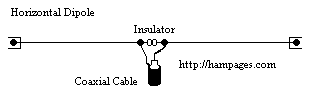
Dipole is a simple antenna, easy to construct. It is widely used by amateurs and it gives satisfactory results in HF Bands. It requires only two points to hook it up. The hight should be about 30 to 35 feet above the ground, or as high as possible. Dipole is considered to be a fundamental antenna based on which more complex types of antennas are designed. It is also called a reference antenna. Most amateurs would be used it at one time or another in their ham career.
The overall length of the dipole is half the wavelength of the frequency for it is used. The length in feet can be calculated by using the formula 468/f MHz. It is cut into two halves and an insulator is used in the center. The radiation pattern of a dipole is like the figure '8'. The radiation is maximum in the broadside of the axis and least in the axis line. The impedance of the dipole is 70 Ohms and a coaxial cable with the impedance of 73 Ohms like RG-59/U is used to match it. Rightly, the dipole can be called the common man's antenna due to its many advantages, like low cost, simple construction, ease of transport, satisfactory results etc. The materials for the dipole are easily obtained and inexpensive. Dipole can be used for local as well a DX working.
In an article on DXpedition, the author has paid the following compliments to the dipole antenna.
"All things considered, dipoles are hard to beat. They pack so light, they will install in almost any tree; in a pinch you can even hang them from your balcony. For 160 through 40 meter, they are almost mandatory. On the other bands, dipoles are pretty effective, especially installed over 30 feet hight"
For the time and money an amateur spends on a dipole, it certainly gives best results and good value for money.
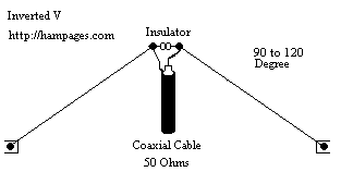
This antenna is a variation of dipole in which the center position is raised to a high point than the ends and hence only one support is required. The ends are to be kept about 10 feet above the ground. The length is little shorter than the dipole. The formula for finding the length of inverted V in feet is 464/f MHz. The angle at the center between the two halves should be between 90 and 120 degree to get best results.
The impedance of inverted V is lower than that of the dipole, ie 50 Ohms. Therefore RG-58/U or RG-8/U co-axial cable is used for the transmission line. Inverted V is a popular and effective antenna and amateurs use it for 20, 40 and 80 meter working.
if one has no space to put up a dipole or inverted V antenna, don't lose heart. This problem has been faced many other hams too. Perhaps it may be possible to go up. So one can try a vertical antenna.
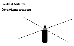
In a vertical antenna the radiating part is quarter wave length and is called the radiator. Copper wire or aluminium tubing can be used for radiator. There are two types of ground vertical and ground plane vertical. For this, the quarter wave length radials are connected to the base and buried in the ground. A ground plane vertical uses an artificial metallic ground usually four rods or wires perpendicular to the antenna.
The radiation resistance of ground plane vertical varies with the diameter of the vertical element. For transmission line a 50 Ohms or 75 Ohms co-axial cable can be used.
The vertical antenna is omni-directional. It radiates or picks up RF energy equally well in/from all direction. This property offers an advantage in DX and contest working. Vertical antenna can be used to monitor even week DX signals and then one can change over to any directional antenna and work that station. Because of its low angle of radiation the signals reach many miles away due to skip propagation. So vertical antenna is better suited for DX working. Hams use it for 80 and 40 meter working.
Multi band vertical can be constructed wherein the vertical section will be quarter wave length at the lowest frequency. For best results, the vertical antenna should be erected as high as possible and far away from metallic objects and tall buildings and trees.
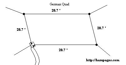
Most city dwellers face the problem of limited space for putting up an antenna of their choice. But if one is lucky and owns a couple of acres of land in a quiet place and the neighbours are co-operative, one can try the 'GERMAN Quad Antenna' designed by a German ham DL3ISA. It is reported that it works well on six bands 80, 40, 20, 15, 10 and even on 2 meters.
The construction is simple and straight forward. Take 83 meters of wire and mount it in the form of a big quad about 30 feet above the ground in a horizontal position. Each side will have a length 20.7 meters. For feed line, use a 75 Ohms co-axial cable. Antenna wire is 2.5 mm soft drawn copper wire. The four preferred directions are the extensions of the quad's diagonals. The ground serves as the reflector for 80 and 30 meters working.
The antenna offers a gain of 6 DB over a dipole mounted at the same hight. On 80 meter, it has a high angle of radiation and distance of 600 miles has been covered. On 40 metres, the radiation pattern is at a lower angle than 80 meters and it has no directivity.
If one has enough space and time he can try this multi-band antenna and work all the six bands and it has no directivity.
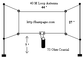
If one is interested mostly only on 40 meter working, he can think of a loop antenna. It is simple and at the same time very effective. For best results, it should be made as square as possible. It should not be made more rectangular as the efficiency will suffer. The overall length of the antenna in feet can be found out by the formula 1005/f MHz. For a resonant frequency of 7.05 MHz the total length of the wire will be 142 feet 6 inches. For antenna wire 16 or 14 SWG wire can be used. Use 75 Ohms co-axial cable for the transmission line. The antenna should be kept at a hight of about 6 feet from the ground level.
If vertical polarisation is desired, feed the loop in the center of the vertical sides. This will give low angle radiation. If one desires horizontal polarisation, feed either to the horizontal sides.
The directivity of the loop antenna is broadside from the loop. So the antenna may be hung in such a way for maximum direction. This loop antenna has 2 DB gain over the dipole. It works well on 20 and 15 meter also with compromising results. For an experimenter, it is an antenna worth giving a trial.
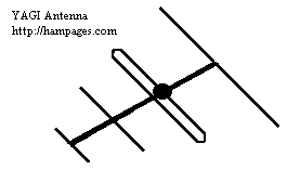
In a beam antenna, two or more dipole elements are used, so the radiated power from the transmitter is added up and focussed in some desired direction, cutting the radiation in other directions. A dipole is used in a beam antenna is called an element and a combination of such elements are called an array.
The simplest beam antenna has two elements. The element into which the power from the transmitter is fed is called the driven element. The second element placed close and parallel to it is called the reflector. RF power from the driven element is induced in the reflector by way of electro magnetic coupling, but it is reflected back and added up the power in the first element and radiated in the forward direction. There is not much power loss in the reflector and all the RF power it receives from the driven element is radiated back. A third element can also be added in the same manner to increase the radiation. This additional element is called director and it is placed in front of the driven element.
The length of the driven element is calculated as half of the wave length and the reflector is 5% longer and director is 5% shorter in length. The spacing between the driven element and the reflector is 0.15 wave length and between director and driven element is 0.1 to 0.2 wave length. The gain obtained from a two element beam antenna is 5 DB and three element antenna offers about 7 DB gain.
It should be noted that the construction of a beam antenna is a complicated job and some construction practice and workshop experience will be necessary. Since the beam antenna radiates all the energy only in the same direction to which it points, a rotator has to be used along with it, to rotate the antenna in all directions to make best use of its directional property.
By : R.V.Shenoy VU2VAS
You are visitor
Since Aug 2000
Website Designed by Yujin Boby, Hampages.com
All Rights Reserved.