|
My Pages |

Conceptual image of my proposed railgun.
Last Update: 2 - 27 - 02 [added
3D pics of a railgun design near bottom of page]
What the heck is a railgun?
The railgun is an electromagnetic device that
uses the fundamental concepts of electricity and magnetism. Most other
railgun sites on the net go into great detail on the theory involved in
railguns, so I will not. If you want to know the theories, here is a great
site: http://www.wpi.edu/~gummi/ph1121.html
Latest design: click to enlarge
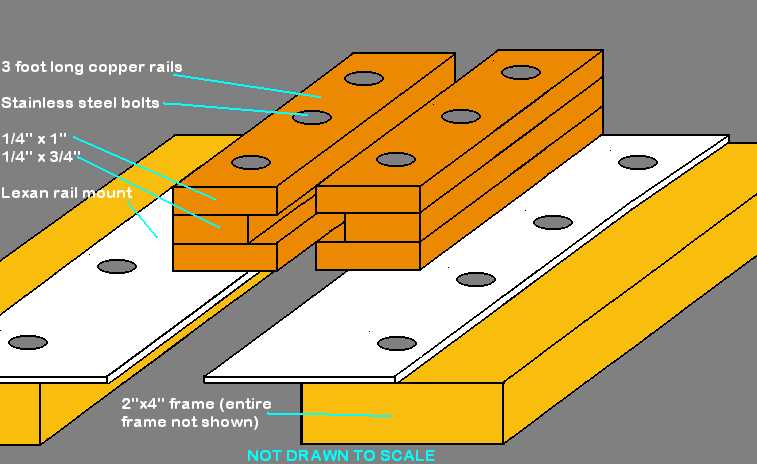
This is a simple design that shouldn't be too difficult to build and
fairly inexpensive. I will build a frame out of 2x4 studs, mount
the rails to it via 3/8" lexan (polycarbonate) with stainless bolts.
The rails are three separate pieces bolted together so as to avoid having
to mill a solid piece of copper. There will be a solenoid to inject the
projectile and energize the rails.
When I finally build a railgun, I will be sure to post the experimental
results. Until then, I will just list some various design possibilities.
Power source:
- Rectified 120V or 240V (for
a small railgun).
- Pulse capacitor, 10kV 240uF
or 20kV 60uF, either are 12,000Joules.
Rails:
- Copper pipes?
- 1" x 1" x 3' solid copper
square stock from McMaster-Carr
Projectile:
- Aluminum projectile fashioned from 1/4" thick sheet
Field coils:
- Probably won't use any on
my pulse-cap powered gun. I have been informed that the magnetic field
produced by such coils would be insignificant as compared to the field
produced by the rails in my high-current pulse cap design.
Updates:
9/7/01 After the big push 2/5/00 to get the project going, it again came to a stop. I got out of college, got a full time job (3rd shift), moved twice, and now engaged to be married. Needless to say the project is indefinite hold. I do plane on completing it but wont start it back up until I have a lab again.
2/5/00 After months of
procrastination I have finally started to put everything together. I plan
on having the gun ready to fire by the end of the month. I hope my layered
copper rail design doesn't introduce losses, but right now most of the design specs are set in stone. I am just going to finish building it and pray
that it will do something when I throw 12kJ of energy at it. Pics will
be coming soon!
7/16/99 I have acquired
a majority of the parts I will need to build a new prototype railgun. The
design will use my 10kV pulse caps and 3' long copper rails. I hope to
start building the railgun next month (august). The picture above is the
design for this gun.
4/14/99 This is actually from the fall of '98. I built a cheap prototype railgun using copper tubes from a hardware store. The projectile used was a penny. To hold the penny in place, and prevent it from flying out of the rails, two long strips of nylon plastic were supported just above and below the center axis. The rails were powered by my two pulse caps, 240uF. The charging supply was a 7kV 120mA NST, controlled with a variac. A custom solenoid threw the penny into the rails were it acted as its own switch.
Results: The prototype was considered a failure in its original form. The one and only test was made at about 4kV charge. As soon as the penny came in contact with the rails, it launched strait up (just made it in front of my upper nylon rail) and left a small dent in the ceiling. There are a few reasons why I think this design is fatally flawed. For one, when the penny first connects the rails, the magnetic field produced by the copper lines coming from the supply is at a 45 degree angle. There may also be to many eddy currents in the penny which may further its effort to jump up rather than down the rails.
Conclusion: I believe that the prototype may yet work if the feed lines are repositioned so they are at the same angle as the rails, and also to lengthen the upper nylon support closer to the injection point. I will also consider making a combination solenoid injector and switch, so that the rails are not energized until the penny is already between the rails and moving. However, I am seriously considering just buying some solid copper rails, which would make things much better.
Pics of the prototype:
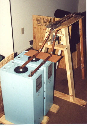
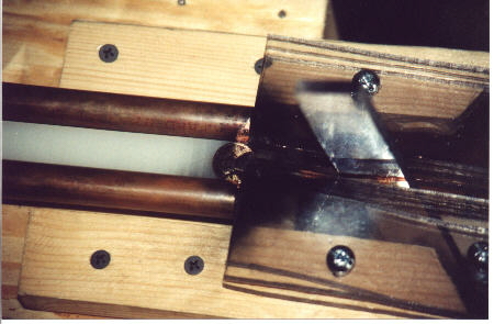
 Here is the new and improved prototype as of 9/9/01. Although I have done
nothing to it in over a year I finally decided to upload a pic of the new
design.
Here is the new and improved prototype as of 9/9/01. Although I have done
nothing to it in over a year I finally decided to upload a pic of the new
design.
3 D MODELS
Ok, so I had a lot of time one day and designed a complete model of my entire conceptual setup. Here are the pics:
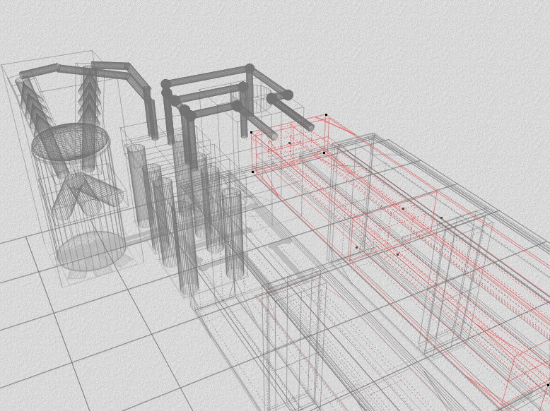 Here is a wireframe of the model.
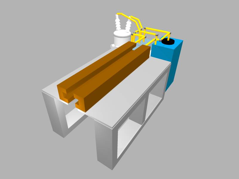

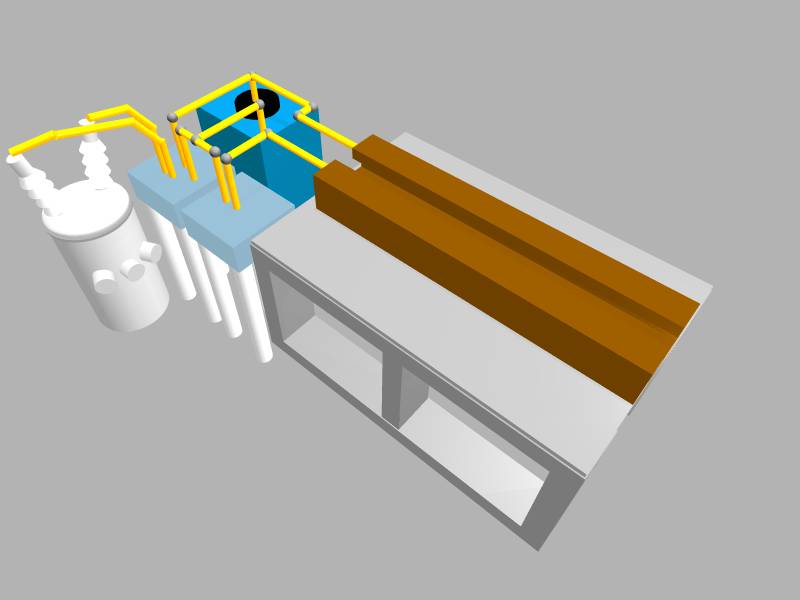
Nothing fancy, but maybe I'll add some textures to the design in the future. The rails are roughly copper color, the transformer is in the rear left, feeding to square light blue boxes which are the rectifier module and switch module. The larger and darker blue object is the capacitor. Wires are the yellow thingies.
This webpage originally born on 4-14-99. Last updated on 2-27-02
Thank you for viewing my web pages!