My home-brew coil winder. I suspect that I shan't want to use this too often! Maintaining a very even lay makes for slow, painstaking work and is hard on the eyes. The motor was donated while the turns counter is simply a Radio Shack lever switch wired across the "=" pad of a cheap calculator. This is OK provided I ALWAYS write down the number of turns I have got to in any section if I leave off.

Initial Design Considerations:
The transformer primary is to be 10,000 ohms. To match this to an 8 ohm load calls for a turns ratio of 35.36:1 The plate resistance of an 845 is 1800 ohms which is equivalent to an inductance of 14.3H at 20Hz. Ideally, I wanted to aim for a primary inductance of more than five times this value, in round numbers, 70H. To cut a long story short, after many iterations (which had to allow for the actual core I would be able to purchase) I came up with a primary of 7200 turns of 28awg wire which with an air gap of 0.008" (two gaps in the magnetic circuit thus a total gap of 0.016") would provide a theoretical inductance of 80H. Having started winding and thus got a better sense of how many turns (primary & secondary) will actually fit in the window, I have revised the primary to 6080 turns, the air gap to 0.007" for a primary inductance of 74H I am quite happy with this result. The DC flux density will be 0.75T and the peak 1.5T. This is higher than would be permissible using a "EI" laminated core. The higher linear flux density means that for the same electrical characteristics, a double C core will need slightly less mass that a "EI" type. Less mass of iron means lower core losses thus lower excitation current and better resolution. The very thin tape (0.002") from which the C cores are wound further reduces the core losses. The primary is wound in 7 full and 2 half sections for a total of 6080 turns. The secondary is interleaved in 8 sections each having 21 turns (multi-filar) for 168 turns total. For a triode, with characteristic low plate resistance, attention to leakage inductance out-weighs that to distributed capacitance. (A pentode, having high plate resistance tends to be loaded down at HF by capacitance. On the other hand with a triode, if the leakage inductance is not controlled, the HF coupling will be impaired which means that the reflected load on the primary will be insufficient to maintain damping and ringing will occur.) However, each primary / secondary adjoining surface forms a shunt capacitance from the primary since the secondary is 'earthy'. To help mitigate this effect, I invested in 5 mil self-adhesive teflon film for the interleave insulation. This has a dielectric constant of 2 which may be compared to a value of 5.9 for the traditional Kraft paper. (Capacitance is directly proportional to dielectric constant.)
7/30/2001:
MKI TRANSFORMER
The prototype transformer ended up having closer to 6800 primary turns, so the ratio is actually around 40:1. The initial results showed severe in-band resonances. A lot of hard thought, math and modelling later and a rational thought occurred to me. With 16 sections (1/2 primary at each end) it was unlikely to be a leakage problem. I already knew that the primary to secondary capacitances were rather high, from 500p (inside layers) to 1200p (outside layers). I know that there are 845 transformers that can do 40k or so without in-band resonances so the question was what do the "other" guys do? Analysis showed that the problem was due to series coupled L-C pairs and it finally occurred to me to reconfigure the primary section connection order. I had them in series, plate at the core, on out. I re-connected (still starting with the plate at the core) the odd sections and the even separately, then connected the odd and even series strings in series with each other. I hope this would mitigate the series L-C interactions and it DID! I now have dead flat response to 20k, a very mild peak just above 20k, a mild dip down to 40k, finally falling off to -3db at 63kHz at 1W.
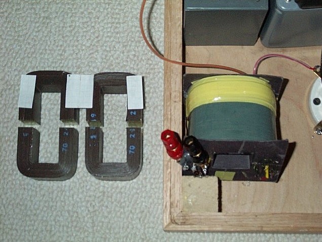
Close up of prototype OPT with double C cores removed. Pieces of paper go between the core ends to create the air gap.
MKII TRANSFORMER
After
some thought, I decided to try again. Experiments on the bench had shown
that I could halve the shunt capacitances by doubling the number of insulation
layers between the sections. To prevent cold flow of the teflon into the
windings, I used one layer of Kraft paper, two layers of teflon then a further
layer of Kraft paper at each primary / secondary interface. The additional
thickness meant that I also had to reduce the number of sections to 14, the
primary being now approximately 6000T and the secondary 175T. the primary
has a half section and each end and 6 full sections.


The first left hand picture shows the MKII transformer at the penultimate layer. Note the secondary windings exiting at the right. The right hand picture shows the completed winding with the C cores. The tape is to prevent the sides from spreading.
Results: The transformer now exhibits a 3dB dip at 23 to 24kHz, rising back to 0dB then rolling off to -3dB at 67kHz. So I now have a dip just above 20kHz rather than a peak. A bit irritating but I feel preferable to a peak. This kind of issue is a consequence of a 10k primary. With much time, patience and copper wire, I most likely could improve the performance. However the transformer is flat 20Hz to 20kHz and other than the dip, the HF extends way out. Moreover, the out-of-band response is smoother than that of MKI which had a 21k peak, a 40k dip then rolled off at 63kHz. In addition, the square wave performance is better with a rise time of 5µseconds which is very respectable, also a bit quicker than MKI. The waveform at 1kHz has very mild overshoot while the waveform at 10kHz now looks like a square wave. The dip is a disappointment but in honesty, I am really quite pleased to have obtained the level of performance I have on my second attempt at an output transformer.


The wires on the right hand view are Litz wire
secondary interconnections. The plate and B+ wires are double insulated
Litz wire and the secondary wires are twin 20awg plus Litz wire. The use
of a clamp rather than the "proper" metal C core straps made
adjustment of the gap much easier.
MKIII TRANSFORMER
Performance measurements were taken using the whole amplifier so include
the interstage transformer and drive circuit.
At full power the rise time is 3microsec. A little overshoot but no
ringing.
I did a full power frequency response characterisation monitoring the input at the
interstage transformer and maintaining this constant:
Reference is 0dB at 1kHz
Flat 50Hz to 50kHz
3dB up at 60k
-3dB point is out past 110kHz. The generator in the HP (339a) stops at 110kHz.
The performance without normalising at the interstage input is not much different,
driven to full power, the -3dB points are around 30Hz and 95kHz. At
less than full power, the LF extends to 0.5dB down at 20Hz. I am
getting 28W into 8 Ohms at 3% THD @ 1kHz. The performance is
tremendously rewarding after all the hours spent winding.
