![]()
![]()
![]()
![]()
![]()
![]()
![]()
![]()
|
|
|
|
The Synopsis running into many pages has been divided into three
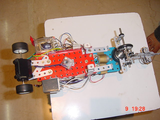
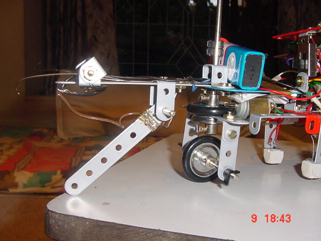
CHASSIS : "THE ANT" is built using the " Mechanix " tools and the various sensors mounted to its main body are also implemented using them. From the bottom view of the robot many of the components can be clearly seen attached to the body. The " Mechanix " tools could be used to obtain any shape and being lighter due to perforations, the payload capacity was highly increased . Being made of iron they are strong and sturdy and there was no question of collapse of the structure . The " Mechanix " tools are basically a set of lego like tools but more sturdy ,since the individual elements are to be joined by nut and screw mechanism. It can be clearly seen from the above picture the individual being joined by nuts. While selection of the material for the main body " Mechanix " was given maximum priority since we thought that it was the best way for us to manipulate as per our requirements. Also since there is no question of machining , we felt that it was the easiest way to go around the problem.
Back to TopSENSORS : "THE ANT" navigation consists of two modes of operation
PATH FOLLOWER MODE :
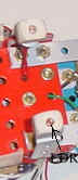
The SPIRIT of the Ant are the LDR sensors which are used for image processing using which the path that has to be traced is decided . These are efficiently coupled to the comparators and the motor driver of the front wheel. The front wheel motor takes care of the turn and precision control guide the robot in the appropriate direction. The careful design of each stage account for its outstanding features such as, low power consumption and high performance in tracing the path even at higher running speeds of the vehicle. The sensors for image processing had been mounted behind the front wheels and at the extreme edges of the chassis. The sensors were adjusted to a level of 5 cm above the ground . The sensors were placed in rubber encapsulation so that light that is reflected from the ground is only absorbed . Also just behind the sensor mechanism a bulb was placed in such a way that the light from the bulb which is reflected picked up by the LDR sensor. This provision was to make the path following feature independent of the external ambient light. The LDR sensors are shown below :
FREE RUNNING MODE: In this mode of operation "THE ANT" is free running and looks out for Obstacles in its path and Huge pits and Valleys.
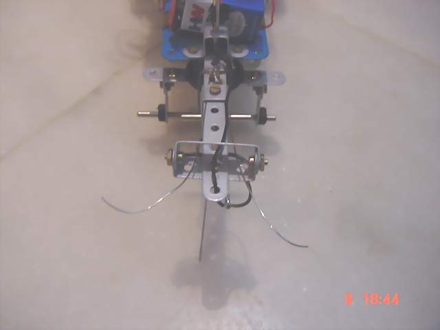
The obstruction detecting whiskers are shown below :
The two whiskers have been connected to one of the terminals and the screws on either side have been connected to another terminal. when the whisker meet an obstacle they make a contact with the screws and the thus the path is completed . The completion of the path reverses the motor direction and the Ant starts moving in the reverse direction. Thus the obstacle is detected before actual collision. Similarly the depth detector consists of a moment that is used as a sensor, when the moment moves above a certain angle the motor turns back and finds a new path. The sensor detects a pit of an arbitrarily predefined depth and prevents it from falling into it.
When the flexible movement falls down to a certain level the base ring gets connected to the movement and thus the path gets completed. The motor reverses and the movement is pulled up . Thus exhibiting an inherent ability to intelligently distinguish obstacles and depth.
Back to Top
Circuit The Circuit diagram of ANT has been split into two parts
The path follower circuit is shown below
The IC description is given below: IC 741 : An operational amplifier is a high gain direct coupled amplifier consisting of many differential amplifiers followed by a level translator and an output stage which is a generally a push-pull or complementary-symmetry pair. This OP-AMP is available as a single integrated circuit, which is an IC741. OP-AMP has a variety of applications, such as ac and dc amplifiers, active filters, oscillators, comparators, regulators, and many more. Here we use the property of the OP-AMP as a comparator to turn the ANT to the left or right in the path follower mode of operation. Since the LDR resistance is proportional to the amount of light falling on it when the LDR is over the black path its resistance is high. In the above circuit this will cause the voltage input to the OPAMP to change as per the resistance of the LDRs. Comparing which is high and which is low, the output of the OP-AMP will switch from positive to negative or vise-a-versa. This activates an amplifier, which turns the motor towards right or left. Thus here we can change the direction of motion of "THE ANT" depending on the light falling or in other words the path below it.
Collision avoiding system circuit is shown below
The working of the circuit and IC is given below: IC 555 : The IC 555 is being used in the circuit to switch the rear driving motor of the ant to move in the backward direction for a specific period of time when the ant meets with an obstacle or a pit. The timer is triggered with the sensors and the working of the timer is explained as below. The relay mechanisms are adjusted in such a way that "THE ANT" moves backward as well as to the left when the sensors are on. Thus "THE ANT" changes its course of motion when it meets with an obstacle or pit. The 555 timer an 8 pin IC, consists of two comparators and a flip-flop a discharge transistor and a buffered output stage. The comparator is an OP-AMP that compares an input voltage with the reference voltage. The reference voltage is applied either at the inverting terminal or at the non-inverting terminal of the OP-AMP. In either case, the output goes into saturation when the non-inverting voltage exceeds the inverting voltage (even by a few hundred micro-volts), and it goes into negative saturation when the inverting voltage exceeds the non-inverting voltage. The reference voltages for the two comparators are developed across a voltage divider arrangement consisting of three resistors of 5kohm each. The upper comparator called as the threshold comparator has a threshold input (pin6) and a control input (pin5) in most applications the control input is not used so that the control voltage equals +2/3 Vcc (it is the voltage developed by the potential divider at point A). The lower comparator called as trigger comparator has a trigger input (pin2) the other input (the non-inverting input) is fed with a constant voltage +vcc/3 developed by the potential divider. The two comparators drive the SR flip flop whenever the threshold voltage exceeds the control voltage the high output from the threshold comparator will reset the flip flop. On the other hand whenever the trigger voltage drops below +vcc/3 the high output from the trigger comparator sets the flipflop. The inverted Q` output of the flip-flop appears at the output (pin3) the Q` output is connected to the base of the discharge transistor too. When Q` is high the transistor saturates and when Q` is low the transistor cuts off. When the external reset (pin 4) is grounded it inhibits the device (prevents it from working) in as in most applications however the external reset is not used and pin4 is tied to the supply voltage. When the relay1 activates the timer circuit is supplied with 12v vcc. Trigger input of the IC555 is always connected to the ground terminal and the trigger input is less than the reference voltage (+vcc/3) hence the trigger comparator output is high, however there is no change in the threshold comparator output hence the input conditions for the flip-flop are r=0 s=1. The flip-flop sets i.e. Q` becomes low. Therefore, at the output (pin3) we get a high output, which makes the led glow. Also the low Q` output cuts off the discharge transistor as the transistor opens the capacitor starts charging through towards +Vcc. When the voltage across the capacitor exceeds +2/3 vcc, the threshold input exceeds the reference voltage and the output of the threshold comparator becomes high. The output of the trigger comparator however is still low hence the conditions for the flip-flop are r=1 and s=0 hence the flip-flop resets Q` output turns high this turns the output (pin3) low thereby turning the led off. Also the high Q` output saturates the discharge transistor which in turn provides a discharge path for the timing capacitor. Thus, the circuit is ready for the next cycle. The delay period i.e. the time for which the led glows is the time taken by the capacitor to charge from 0v to 2/3vcc In seconds it is given as T=1.1RC Where R is in ohms And c is in farads. In practice R should not exceed 20megaohm while selecting an electrolytic capacitor for C a low leakage unit is selected Here the IC 555 timer provides a time interval that is virtually independent of the supply voltage vcc unlike in many other RC timers this is because the charging rate of c and reference voltages of the comparators are directly proportional to the supply voltage the operating voltage can range from 4.5v to 18 v maximum. The capacitor charges from 0 to 2/3vcc T=1.61 RC Once triggered the circuit cannot respond to additional trigger until the time interval has elapsed. Thus the ANT takes an alternate course and continues to navigate. Back to Top Next Previous |
|
|