I think I have always
been inspired by the heavens above. My first true exploration
into this began when I was young helping my father with the construction
of his 6" telescope. He had ground the mirror himself and
my contribution was the making of a mount for it. With completion
of that telescope came many glorious views. The two things which
really fired my imagination were the breathtakingly close views
of the cratered moon and especially seeing Saturn with it's multitude
of rings. In a way it seemed so foreign and bizarre and yet there
it was right above me. These experiences were my first immersion
into this wonderful "world".
Since then this interest
has become inextricably linked with my interest in horology (clocks).
If anything has mass and is in proximity to something else it
will orbit. If it orbits it has a period. If it has a period a
clock can replicate it. Thus goes the quest of modeling the heavens.
It is age old. Geared mechanisms modeling the heavens (such as
the Antikythera mechanism) have been built for centuries. I have yet to make
anything like an orrery or an astronomical clock but is my greatest
hope to do so some day. Below (and in my Wallingford clock section) are some of my first feeble steps toward
that end.
Some Star Trail Photography
Here are the results
of some ongoing experiments with star trail photography. If you
don't know what star trail photography is it is a photographic
representation of the Earth spinning. One takes a time exposure
of the night sky. Since the Earth will naturally move during that
exposure time the effect is that the stars in the night sky will
appear as "trails", generally circular about the pole.
The effect if captured right can produce some remarkable pictures
that truly instill the sense of passing time.
My first attempt into
this foray was unsuccessful. I did not get the exposure settings
right at all (greatly underexposed) and the result was much like
the present background. After doing some further research I have
found the following table
helpful as a starting point.
Below is my second
attempt. In this case I used the table to set the exposure. The
exposure started at about 9:30pm and was facing north. The sky
was darker than it appears in the photograph. I suspect it was
picking up a lot of dusk light as in summer time the sun dips
below the northern horizon at a low angle. At the end of this
shot when I went out to close the shutter the I noticed the lens
was heavily covered in dew. In my opinion the star trails were
shorter than I was looking for.
 Canon A1 with FD 24mm/f2.8 lens at 400ASA (Kodak Max),
Exposure 2hr @ f4.
Given the issue with
the dew I made a dew prevention optic heater base on the design
of Mark Kaye.
I made it to be powered from the cigarette lighter of a vehicle.
Below are my 3rd and 4th attempts. In this case in there was a
haze on the horizon if I shot in the direction above so I repositioned
my set up to shoot facing east. At the time of the shooting the
optic heater wasn't complete so I simply wrapped the heater element
around the lens, covered it with insulating shop rags and tied
it up with a string. The shot on the left was set for 3 hours
but at the end of the exposure I found the shutter had already
closed as the camera battery had run out. The shot on the right
was taken the following night with a fresh battery and it went
the full 3 hours. I actually fell asleep waiting for the 3 hours
to go by and when I woke up noticed that the moon had risen. This
is not the effect I wanted but it is interesting to note that
it did not completely ruin the shot like I thought it might. The
star trails are getting better but I still think an even longer
exposure is needed. Having captured this shot I should note that
the camera was unable to take pictures the following day as the
new battery had completely drained taking the picture. The optic
heater worked flawlessly and the lens was completely dry. As a
comparison the tripod was wet with dew droplets.
Canon A1 with FD 24mm/f2.8 lens at 400ASA (Kodak Max),
Exposure 2hr @ f4.
Given the issue with
the dew I made a dew prevention optic heater base on the design
of Mark Kaye.
I made it to be powered from the cigarette lighter of a vehicle.
Below are my 3rd and 4th attempts. In this case in there was a
haze on the horizon if I shot in the direction above so I repositioned
my set up to shoot facing east. At the time of the shooting the
optic heater wasn't complete so I simply wrapped the heater element
around the lens, covered it with insulating shop rags and tied
it up with a string. The shot on the left was set for 3 hours
but at the end of the exposure I found the shutter had already
closed as the camera battery had run out. The shot on the right
was taken the following night with a fresh battery and it went
the full 3 hours. I actually fell asleep waiting for the 3 hours
to go by and when I woke up noticed that the moon had risen. This
is not the effect I wanted but it is interesting to note that
it did not completely ruin the shot like I thought it might. The
star trails are getting better but I still think an even longer
exposure is needed. Having captured this shot I should note that
the camera was unable to take pictures the following day as the
new battery had completely drained taking the picture. The optic
heater worked flawlessly and the lens was completely dry. As a
comparison the tripod was wet with dew droplets.

 Left - Canon
A1 with FD 24mm/f2.8 lens at 400ASA (Kodak Max), Exposure 3hr?
@ f5.6 Right - Canon A1
with FD 24mm/f2.8 lens at 400ASA (Kodak Max), Exposure 3hr @ f5.6.
As of fall 2003 I was
in the process of making a 12V to 6V regulator to power the camera
through a machined, simulated, battery (basically a plastic slug
with brass ends wired to the regulator). As exposures get longer
this power source was needed especially as a battery is $12 and
I get one picture out of it. I also experimented if a clock timer
could be used to shut down the exposure once preset. The plan
was to allow me to set up the exposure in the evening and retrieve
the camera in the morning without having to stay awake for several
hours in complete darkness. The following few paragraphs show
my design but I'm sure it could be adapted to many arrangements.
Left - Canon
A1 with FD 24mm/f2.8 lens at 400ASA (Kodak Max), Exposure 3hr?
@ f5.6 Right - Canon A1
with FD 24mm/f2.8 lens at 400ASA (Kodak Max), Exposure 3hr @ f5.6.
As of fall 2003 I was
in the process of making a 12V to 6V regulator to power the camera
through a machined, simulated, battery (basically a plastic slug
with brass ends wired to the regulator). As exposures get longer
this power source was needed especially as a battery is $12 and
I get one picture out of it. I also experimented if a clock timer
could be used to shut down the exposure once preset. The plan
was to allow me to set up the exposure in the evening and retrieve
the camera in the morning without having to stay awake for several
hours in complete darkness. The following few paragraphs show
my design but I'm sure it could be adapted to many arrangements.


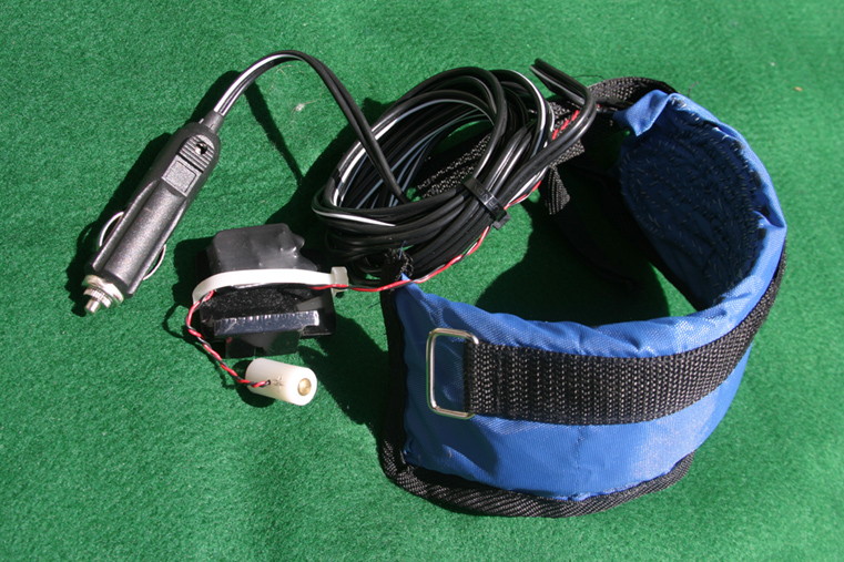
 The above pictures
show the cigarette lighter powered heater core (left). The heater
has yet to be sewn into a lens blanket. The heater core is basically
a strip of nichrome wire (covered in yellow heatshrink). The wire
is of a length that will cause about 5W dissipation (12Vx12V/5W
= 28.8 ohms). The blanket is an exercise wrist weight cut open,
stripped of its weights and the heater sewn in serpentine fashion
(the middle two pictures above show this in progress). Once the
nichrome was sewn in two strips 0.14" thick (each) of neoprene
are encapsulated in the heater blanket as insulators. The ends
of the nichrome are soldered to the 12V cigarette lighter cord.
Lens dew now solved!
The above pictures
show the cigarette lighter powered heater core (left). The heater
has yet to be sewn into a lens blanket. The heater core is basically
a strip of nichrome wire (covered in yellow heatshrink). The wire
is of a length that will cause about 5W dissipation (12Vx12V/5W
= 28.8 ohms). The blanket is an exercise wrist weight cut open,
stripped of its weights and the heater sewn in serpentine fashion
(the middle two pictures above show this in progress). Once the
nichrome was sewn in two strips 0.14" thick (each) of neoprene
are encapsulated in the heater blanket as insulators. The ends
of the nichrome are soldered to the 12V cigarette lighter cord.
Lens dew now solved!


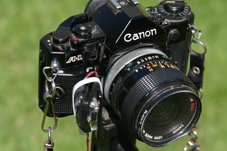
 The "DarylCell"
battery (left) is made of nylon drilled through at 1/8" with
a central hole at 90° for wire egress. Each end was then drilled
1/4" dia by 1/4" deep. 1/4" brass rod was cut 0.280"
long, slightly rounded at one end and drilled with a #59drill
at the other end. A red & black wire was fed into the 90°
hole and out each end. Each wire was then soldered to the brass
end piece's #59 hole. Then end pieces were then pressed into the
nylon until the length matched a real battery. This battery simulator
was then connected to a TO-220 linear regulator circuit that receives
12V from the cigarette lighter cord and steps it down to 6V for
the "DarylCell" camera battery. The regulator is mounted
to a piece of steel shaped to hold the battery in place while
letting the "DarylCell" battery wire egress out of the
camera to the regulator. Since the camera battery door is left
open in use, to allow the battery wire out, I make use of the
removable plastic handgrip cap (by Canon - 2nd left picture above)
which screws in place to hold and retain everything in place (right
picture) i.e. the regulator and plate are retained by Canon's
own handgrip piece. Camera power now solved! Not only that but
a previous problem (battery drain) has now been turned into an
opportunity (automatic shutdown) as you'll see next.
The "DarylCell"
battery (left) is made of nylon drilled through at 1/8" with
a central hole at 90° for wire egress. Each end was then drilled
1/4" dia by 1/4" deep. 1/4" brass rod was cut 0.280"
long, slightly rounded at one end and drilled with a #59drill
at the other end. A red & black wire was fed into the 90°
hole and out each end. Each wire was then soldered to the brass
end piece's #59 hole. Then end pieces were then pressed into the
nylon until the length matched a real battery. This battery simulator
was then connected to a TO-220 linear regulator circuit that receives
12V from the cigarette lighter cord and steps it down to 6V for
the "DarylCell" camera battery. The regulator is mounted
to a piece of steel shaped to hold the battery in place while
letting the "DarylCell" battery wire egress out of the
camera to the regulator. Since the camera battery door is left
open in use, to allow the battery wire out, I make use of the
removable plastic handgrip cap (by Canon - 2nd left picture above)
which screws in place to hold and retain everything in place (right
picture) i.e. the regulator and plate are retained by Canon's
own handgrip piece. Camera power now solved! Not only that but
a previous problem (battery drain) has now been turned into an
opportunity (automatic shutdown) as you'll see next.
 Above is the device
(the white thing) which makes the timing easy. It is an Intermatic
battery powered, digital, wall switch timer. It is intended to
switch AC power ON and OFF at intervals you program (or set) into
the clock. The actual switch inside is an isolated form-A relay
contact. Since the DC levels are low it works fine in this application.
I picked it up at Home Hardware for about $45 and put it into
a metal box. At Canadian Tire I bought a cigarette lighter extension
cord. I made it so the male end is the input and the female end
(for the heater/"DarylCell" arrangement to plug into)
is the output. I cut one lead in the middle and spliced in the
timer so as to switch that lead ON and OFF. If you have trouble
staying awake to stop the exposure this thing is the "cat's
ass". Canon's A1 needs the battery to hold the shutter open.
Kill power and the exposure is stopped which is exactly what I
want here. I also use it to stop the heater as well so as not
to drain the car battery too much.
Above is the device
(the white thing) which makes the timing easy. It is an Intermatic
battery powered, digital, wall switch timer. It is intended to
switch AC power ON and OFF at intervals you program (or set) into
the clock. The actual switch inside is an isolated form-A relay
contact. Since the DC levels are low it works fine in this application.
I picked it up at Home Hardware for about $45 and put it into
a metal box. At Canadian Tire I bought a cigarette lighter extension
cord. I made it so the male end is the input and the female end
(for the heater/"DarylCell" arrangement to plug into)
is the output. I cut one lead in the middle and spliced in the
timer so as to switch that lead ON and OFF. If you have trouble
staying awake to stop the exposure this thing is the "cat's
ass". Canon's A1 needs the battery to hold the shutter open.
Kill power and the exposure is stopped which is exactly what I
want here. I also use it to stop the heater as well so as not
to drain the car battery too much.

 On the left you can
see the whole power/heater arrangement installed while on the
right the camera is set-up for exposure. The timer (male) is plugged
into the cigarette lighter in the car and sits on the front seat.
The tripod is set up close to the car and the heater arrangement
(male) is plugged into the timer (female) inside the car. To take
a picture you first make sure the timer is ON and the shut-off
time is programmed in. While it's still light I will compose the
direction of the shot with foreground objects and set the focus
to infinity, set the camera exposure time to "B" (bulb).
When it's dark and you're ready to go you plug in the heater,
confirm the camera is powered, do a last verify all things are
OK and close the eyepiece shutter to prevent light back feeding
in through the eye-piece. When the start time has arrived you
use the cable release to lock the shutter open. At this point
you can walk away and retrieve everything in the morning if you
want to. For those interested the basic schematic is here.
The following shows
my next attempt (#5). While I still consider it a failure it is
interesting. It also demonstrated to me that all the above equipment
works excellently. I brought the above equipment with me on my
2004 vacation up north in the hope of some good photographic opportunities.
Unfortunately we were either in towns or it was overcast. The
day the picture was taken it had been cloudy all that day so I
never thought I would be able to attempt a shot. While sitting
at the picnic table by the campfire having an enjoyable discussion
with my wife I noticed that all of a sudden the stars were visible.
I quickly set up for a long exposure and let it go then went back
to the table to continue the discussion. We later packed it in
before the shot was completed. The first thing I notice in the
exposure (apart from the splotches from my crappy scanner) was
it was less clear than I thought. The second is the smaller aperture
(f8) seems to make finer (more narrow) star trails however at
over 5 hours they are certainly long now. Another thing is while
it looked dark at the time there is obviously some settlement
across the river which caused some unanticipated light pollution
(glow & red lights). This is getting to be a recurrent problem
and one I will have to devote more time to avoiding in future.
I think in this location however if it wasn't overcast on the
horizon the settlement light-glow would have been greatly reduced.The
lighting of the tree and the tent by the fire is neat. The campfire
was in reality low but looks like a blowing hot foundry fire in
the picture yet I'm surprised it didn't over-expose the 5.25 hour
shot. Finally my wife and I being ghostly visible in the shot
by the picnic table are another interesting indication of the
passing of time. For a "what the hell lets give it a try"
shot it does have some interesting things in it to learn from
.
On the left you can
see the whole power/heater arrangement installed while on the
right the camera is set-up for exposure. The timer (male) is plugged
into the cigarette lighter in the car and sits on the front seat.
The tripod is set up close to the car and the heater arrangement
(male) is plugged into the timer (female) inside the car. To take
a picture you first make sure the timer is ON and the shut-off
time is programmed in. While it's still light I will compose the
direction of the shot with foreground objects and set the focus
to infinity, set the camera exposure time to "B" (bulb).
When it's dark and you're ready to go you plug in the heater,
confirm the camera is powered, do a last verify all things are
OK and close the eyepiece shutter to prevent light back feeding
in through the eye-piece. When the start time has arrived you
use the cable release to lock the shutter open. At this point
you can walk away and retrieve everything in the morning if you
want to. For those interested the basic schematic is here.
The following shows
my next attempt (#5). While I still consider it a failure it is
interesting. It also demonstrated to me that all the above equipment
works excellently. I brought the above equipment with me on my
2004 vacation up north in the hope of some good photographic opportunities.
Unfortunately we were either in towns or it was overcast. The
day the picture was taken it had been cloudy all that day so I
never thought I would be able to attempt a shot. While sitting
at the picnic table by the campfire having an enjoyable discussion
with my wife I noticed that all of a sudden the stars were visible.
I quickly set up for a long exposure and let it go then went back
to the table to continue the discussion. We later packed it in
before the shot was completed. The first thing I notice in the
exposure (apart from the splotches from my crappy scanner) was
it was less clear than I thought. The second is the smaller aperture
(f8) seems to make finer (more narrow) star trails however at
over 5 hours they are certainly long now. Another thing is while
it looked dark at the time there is obviously some settlement
across the river which caused some unanticipated light pollution
(glow & red lights). This is getting to be a recurrent problem
and one I will have to devote more time to avoiding in future.
I think in this location however if it wasn't overcast on the
horizon the settlement light-glow would have been greatly reduced.The
lighting of the tree and the tent by the fire is neat. The campfire
was in reality low but looks like a blowing hot foundry fire in
the picture yet I'm surprised it didn't over-expose the 5.25 hour
shot. Finally my wife and I being ghostly visible in the shot
by the picnic table are another interesting indication of the
passing of time. For a "what the hell lets give it a try"
shot it does have some interesting things in it to learn from
.
 Canon A1 with FD 24mm/f2.8 lens at 400ASA (Kodak Max),
Exposure 5.25hr @ f8.
To be continued...
Canon A1 with FD 24mm/f2.8 lens at 400ASA (Kodak Max),
Exposure 5.25hr @ f8.
To be continued...
Handy Links

- The Ottawa Clear Sky Clock above (Dark
is good/White is bad - click blocks for map. Many other good
links here!)
- Ottawa
Light Polution Map (Montreal is the
bright spot on the extreme right, Canada/US boarder is the white
line)
- Complete Sun & Moon Data
(Canadians go down to Form B)

Current phase of the Moon updated
every 4 hours - but only if you refresh your browser ;-)
An 18" Brass Horizontal
Sundial


 Years later after I
had left school my mother had expressed a desire for a sundial
while we were looking through a Harrowsmith magazine. I decided
I would make a pair of them giving her one for Christmas. My plan
started off as a simple time scale. It was while researching them
that I found out how accurate they can be and how they can show
many of the motions of the Earth around the sun. So, as with most
of my projects, what started out as a simple time scale soon blossomed
into a full featured sundial. I kept learning by adding each bit
of "furniture" (a sundial term for features) and understanding
its background. By the time the design was completed I had a pretty
sound intuitive understanding of the intricacies of the yearly
solar movement and how it appeared in the sky.
I did the graphic design
on a fridge size computer (this was back in the 80's) which would
spit it's 2D output to an HP pen plotter. When the design was
complete it would take 45 minutes to come up on the screen! I
plotted out the nearly completed design and after some final hand/pen
work I sent it out to get positives and negatives made. These
were large as this was to be an 18" diameter dial (needed
for minute resolution). After obtaining 3/8" thick brass
plate for the dials and 1/2" thick brass plate for the gnomens
I set about getting the gnomen machined at work (this predated
my own metalworking capability but helped create my desire to
get into it). The gnomen had to have a 46° angle machined
into it. Additionally it was to have a nodus (notch) in the style
(top edge). The shadow of this notch would be used to track the
position of the Sun on the dial (see the map on the center picture
above). After the gnomens were machined I set into etching the
design work into the brass.
I had to make a photo-chemical
etching studio at home. One first polishes the brass then under
red light conditions applies the liquid (honey like) photo resist
spreading it evenly over the entire surface. After waiting for
it to dry you then give it a gentle bake in the oven. When dry
like this it is very light sensitive. At this point you lay on
your positive artwork and expose the piece to ultraviolet light,
in my case 6 minutes at 2ft. After exposure you develop it by
placing the piece in a tub and washing the developer back and
forth over it for a predetermined period of time (2 minutes in
my case) followed by a rinse. The photo-resist is very soft and
susceptible at this point. This point was the source of most of
my imperfections as it is difficult to manipulate the sheer mass
of the plate through the processes when the resist gets so vulnerable.
This also made double sided etching of the gnomen a screaming
bitch. After it is developed it is carefully dried by another
gentle bake in the oven. At this point there is a plastic like
coating over the entire piece except were the artwork had a black
line. Where ever there is a black line the resist does not get
exposed to UV and hence is washed away in the developing process
leaving exposed brass. All that is required now is to put the
piece back in a tub and wash an etchant over it (ferric chloride
or ammonium persulphate). This will eat into the exposed brass.
I went for a deep 0.040" etch. At this point the process
gets fun because now you have a plastic coating with etched lines.
You simply spray paint the entire piece black then after it's
dry you get a flat block with emery paper and begin to sand. Its
fun to watch the finished pattern jump out at you as you sand
off the painted resist. The paint bonds well to the freshly etched
lines and being in a groove is protected from sanding while the
painted resist quickly sluffs off. You just progress to finer
and finer emery until the brass is shiny and polished. Then you
spray a lacquer coat to protect the exposed brass.
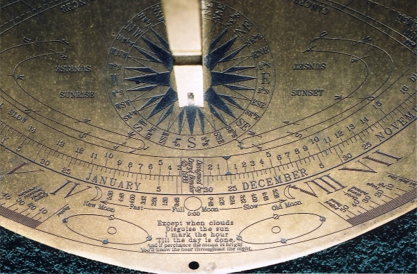
The pictures above
show the dial. It's nearly 15 years old now so its lost it's original
luster but the deep etch has held up remarkably well. It has the
following features: minute resolution, noon marks for cites around
the world, equation of time correction, lines of declination,
latitude marks, date, sign that the sun is in, day length, solar
azimuth or compass heading, solar altitude, time and direction
of sunrise and sunset, corrections for telling time by the moon,
a map projection which, used in conjunction with the nodus on
the style, allows the sun's progress throughout the day to be
watched.
As I said, the second
dial (not shown) was given to my parents as a Christmas gift and
to this day it sits in one of the gardens at their home. Being
outdoors for 15 years the lacquer has long since disappeared and
hence their dial has a darker colour but, given the deep etch,
the time is still easily read.
It still amazes me
that an immovable lump of metal (albeit with carefully marked
lines) can give so much astronomical information.
Years later after I
had left school my mother had expressed a desire for a sundial
while we were looking through a Harrowsmith magazine. I decided
I would make a pair of them giving her one for Christmas. My plan
started off as a simple time scale. It was while researching them
that I found out how accurate they can be and how they can show
many of the motions of the Earth around the sun. So, as with most
of my projects, what started out as a simple time scale soon blossomed
into a full featured sundial. I kept learning by adding each bit
of "furniture" (a sundial term for features) and understanding
its background. By the time the design was completed I had a pretty
sound intuitive understanding of the intricacies of the yearly
solar movement and how it appeared in the sky.
I did the graphic design
on a fridge size computer (this was back in the 80's) which would
spit it's 2D output to an HP pen plotter. When the design was
complete it would take 45 minutes to come up on the screen! I
plotted out the nearly completed design and after some final hand/pen
work I sent it out to get positives and negatives made. These
were large as this was to be an 18" diameter dial (needed
for minute resolution). After obtaining 3/8" thick brass
plate for the dials and 1/2" thick brass plate for the gnomens
I set about getting the gnomen machined at work (this predated
my own metalworking capability but helped create my desire to
get into it). The gnomen had to have a 46° angle machined
into it. Additionally it was to have a nodus (notch) in the style
(top edge). The shadow of this notch would be used to track the
position of the Sun on the dial (see the map on the center picture
above). After the gnomens were machined I set into etching the
design work into the brass.
I had to make a photo-chemical
etching studio at home. One first polishes the brass then under
red light conditions applies the liquid (honey like) photo resist
spreading it evenly over the entire surface. After waiting for
it to dry you then give it a gentle bake in the oven. When dry
like this it is very light sensitive. At this point you lay on
your positive artwork and expose the piece to ultraviolet light,
in my case 6 minutes at 2ft. After exposure you develop it by
placing the piece in a tub and washing the developer back and
forth over it for a predetermined period of time (2 minutes in
my case) followed by a rinse. The photo-resist is very soft and
susceptible at this point. This point was the source of most of
my imperfections as it is difficult to manipulate the sheer mass
of the plate through the processes when the resist gets so vulnerable.
This also made double sided etching of the gnomen a screaming
bitch. After it is developed it is carefully dried by another
gentle bake in the oven. At this point there is a plastic like
coating over the entire piece except were the artwork had a black
line. Where ever there is a black line the resist does not get
exposed to UV and hence is washed away in the developing process
leaving exposed brass. All that is required now is to put the
piece back in a tub and wash an etchant over it (ferric chloride
or ammonium persulphate). This will eat into the exposed brass.
I went for a deep 0.040" etch. At this point the process
gets fun because now you have a plastic coating with etched lines.
You simply spray paint the entire piece black then after it's
dry you get a flat block with emery paper and begin to sand. Its
fun to watch the finished pattern jump out at you as you sand
off the painted resist. The paint bonds well to the freshly etched
lines and being in a groove is protected from sanding while the
painted resist quickly sluffs off. You just progress to finer
and finer emery until the brass is shiny and polished. Then you
spray a lacquer coat to protect the exposed brass.
The pictures above
show the dial. It's nearly 15 years old now so its lost it's original
luster but the deep etch has held up remarkably well. It has the
following features: minute resolution, noon marks for cites around
the world, equation of time correction, lines of declination,
latitude marks, date, sign that the sun is in, day length, solar
azimuth or compass heading, solar altitude, time and direction
of sunrise and sunset, corrections for telling time by the moon,
a map projection which, used in conjunction with the nodus on
the style, allows the sun's progress throughout the day to be
watched.
As I said, the second
dial (not shown) was given to my parents as a Christmas gift and
to this day it sits in one of the gardens at their home. Being
outdoors for 15 years the lacquer has long since disappeared and
hence their dial has a darker colour but, given the deep etch,
the time is still easily read.
It still amazes me
that an immovable lump of metal (albeit with carefully marked
lines) can give so much astronomical information.
A 10" Astrolabe
If you are into astronomy
and you don't know how an Astrolabe works you should! It is essentially
an analog computer for the heavens and it's effect is absolutely
magical once you understand it.
My involvement started
one day while I was perusing a book store sale I came across a
$2 book about time. It had the most remarkable instrument on the
cover, an astrolabe. I bought the book. The more I looked at the
cover the more I was driven to understand how this instrument
worked. While I could figure out much by looking at it there were
a few things which continued to baffle me. Eventually I bought
another book, Colin Ronan's "The Practical Astronomer"
(an inexpensive but great book), which finally gave me the basic
understanding I was looking for. Once I grasped the principles
I simply had to make one. I mean if I could make a sundial why
couldn't I make one of these. Again the design started off simple
but after some discussion on rec.crafts.metalworking I was put
onto yet another book, Harold N Saunder's "All The Astrolabes".
Here was a book which described nearly everything including many
other types of astrolabes other than the planispheric type I had
undertaken. While out of print I would highly recommend this book
if you want to fully understand astrolabes. The only thing it
did not explain, surprisingly, was how to create the date/zodiac
translation scales. I reasoned that out on my own.
I started into the
design with a newly obtained MAC program called Generic CAD. A
rudimentary 2D CAD program. It had one basic flaw. In order to
make text follow curves each letter of text had to be placed one
by one. It was made more difficult by the fact that the letter
of text was within 4 corner squares of an invisible text box.
When you printed it out the letter would drop to the bottom of
the text box so I had to predict in advance where the letter would
be when it printed out. That's one thing when you have under a
100 letters but when you have thousands upon thousands it gets
tricky.
I won't get into how
an astrolabe works, you can read about that here but suffice it to say armed with the
knowledge contained in the Ronan & Saunders books the design
blossomed to a great level of complexity. Instead of a single
solar hand my design has three. The Sun, Moon and Nodes. The artwork
for the back of the matter can be seen in the background of my
creative pursuits page but that is only the beginning. There are 18
different latitude plates as well as a horizon plate for determining
latitude and of course the movable rete. There is such a job ahead
in etching that I have not realized this piece yet. In addition
they have discontinued the photo-resist I used to buy. The etching
as a result will likely have to be professionally done. The design
has been tested, however, by plotting out versions and attaching
them to cardboard. Happiness is seeing your design work in Canada
and, with a different plate, in St Lucia (what a night sky!!)
or having it predict an eclipse and that it would be a grazing
one at that!
A Vertical Declining
Dial
This is a dial I started
in the winter of 2001/02. I actually started in the fall of 2001
by determining my latitude, longitude and the amount the wall
I wanted to mount the sundial to declined toward the west. The
first two became trivial with the purchase of a inexpensive GPS
unit. The latter took several readings over a week. I used the
approach of measuring the shadow cast by a stick perpendicular
to a wall at a specific time & date. Once the shadow is measured
and the time, date, latitude and longitude are known the angle
of the wall from true south can be calculated. I made an Excel
spreadsheet program to do the number crunching. In the end I had
3 measurements which provided wall declinations within 0.25°
and two of those within 0.01°.
I made another Excel
spreadsheet which calculated the hour line angles, the angle of
the shadow casting style and it's angle from the vertical noon
line. I wanted to add declination lines so I modeled everything
on Pro/E (industrial CAD software) but found while it worked it
was cumbersome if I wanted an analemma. I then went back to trying
to integrate declination information into my Excel sheet. It was
while searching for some of the basic trigonometric formula that
I bumped into the Shadows
program which did nearly everything I was trying to do. The more
I played with it the more I was impressed to the point where I
abandoned my similar but non-graphic approach and relied on the
program to provide the basic outlay for construction. It even
factors in the longitudinal distance from your standard meridian.
By doing this you have the *full* conversion from local apparent
(sundial) time to watch time. The artwork design is a conglomeration
of many things I liked about other dials I had seen such as the
Sun emblem and the "time ribbon". Others are similar
in concept but unique to this dial such as the Ottawa River scene.
To my knowledge the end of the declination "web" terminating
in a sunset followed by night is a first (some others simply flat-line
the web at the sunset point). The idea here was that at a glance
you could tell approximately when civil, nautical & astronomical
twilight occur which would be useful for star-gazing. The constellation
figures on the declination "web" are ala Hevelius.
My plan was to mount
the dial below a front bedroom window. Given the existing trim
there is a natural place for it below that window so that led
to it's basic dimensions of 43.25" x 44". The idea was
to make it from some extra 1/2" Baltic birch plywood I obtained
when making my CD stands. The problem I had then was to get a
1:1 plot from the Shadows program for the size of dial I wanted.
In the end it was Gilmore Reproductions that helped me out with the large plot. Then due to
other obligations I set this project aside for a year. This is
typical. My projects do tend to leap frog one over the many others
before leaping again.
When I got back into
it around Christmas 2002 I decided to begin painting the dial
The paint I chose was marine paint. Expensive but tough! I wanted
this dial to stand up to the elements for a long time. I decided
on Hatteras White for the declination "web", red for
the line work within the "web", a light blue for the
sky background, yellow for the sun, black for the line work, numbers
and general tinting while white was chosen for the hour ribbon
and for lightening other colours. Finally, for the trees etc in
the lower right scene, I already had some Malachy green I had
used previously on my Jacob Kayak.
The only deviation from marine paint was the sunset, with its
multitude of colours, where I used model enamel.
In getting ready to
paint the first thing that was discovered was that the centerlines
of the Shadows plot didn't match the corresponding centerlines
of the dial. After some investigation I found that while all sides
of the dial were parallel to each other the dial was slightly
trapezoidal (not square). Slight as the problem was it had to
be solved as the layout on the dial had to be true if the dial
was to work properly. My solution was to use my beam compass and revert
to Euclidian geometry. Once the dial was trued the declination
web was transferred from the plot to the dial. With that in place
I purchased a splendid 3M overhead projector from Advantage Audio
Visual Rentals (Thanks
Jeff!) and used it to transfer other artwork such as the time
ribbon and the Ottawa River scene etc to the dial. After that
it was basically many sessions of painting and projecting and
more painting. I had never done "artistic" painting
before so this was a learning experience.
I decided early on
that the gnomen etc was to be made of brass for two main reasons.
First I didn't want rust stains developing over the dial and secondly
it would be easy to fabricate using my torches & SIL-FOS solder.
It would also be easy to machine the sun emblem that I had planned
to cast a shadow on the declination "web". I picked
up the brass for it at Loucon Metal
where I normally pick up most of my steel. While I originally
designed a large opaque perforated disc to be the sun emblem I
later changed the design to the inverse of that (a radiant cross-haired
ring) as I found it had a more realistic and brighter look.
.
to be continued.....