 Marking the stabilizer top skin for drilling.
These photos show the Horizontal Stabilizer and Elevator construction sequence. New photos will be added at the top, so start at the bottom and work your way up by date.
Marking the stabilizer top skin for drilling.
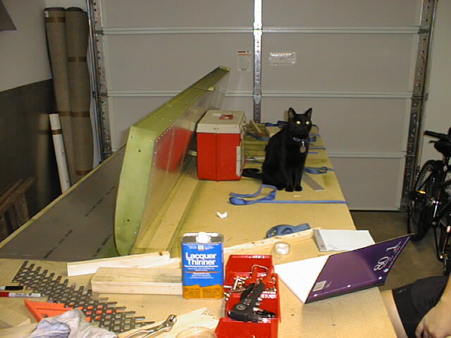 Onyx the Quality Control Cat checking my work.
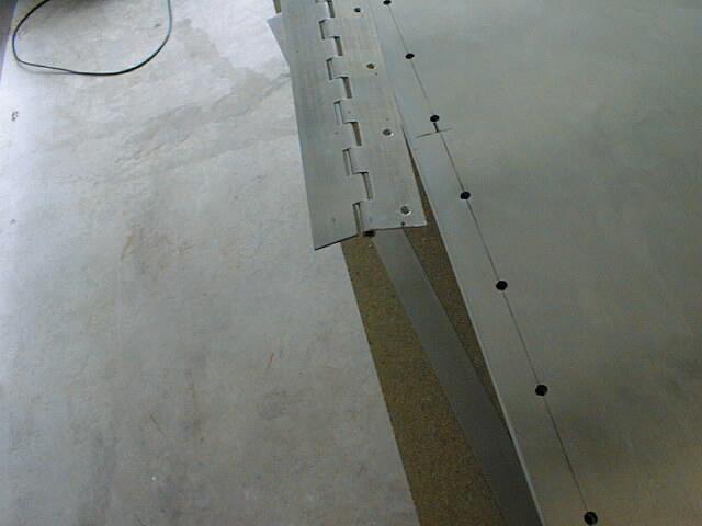
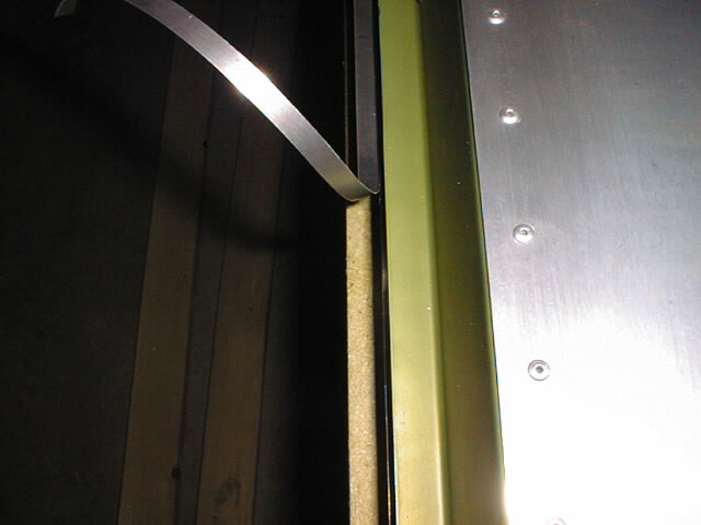 Trimming the top skin flush with the rear spar.
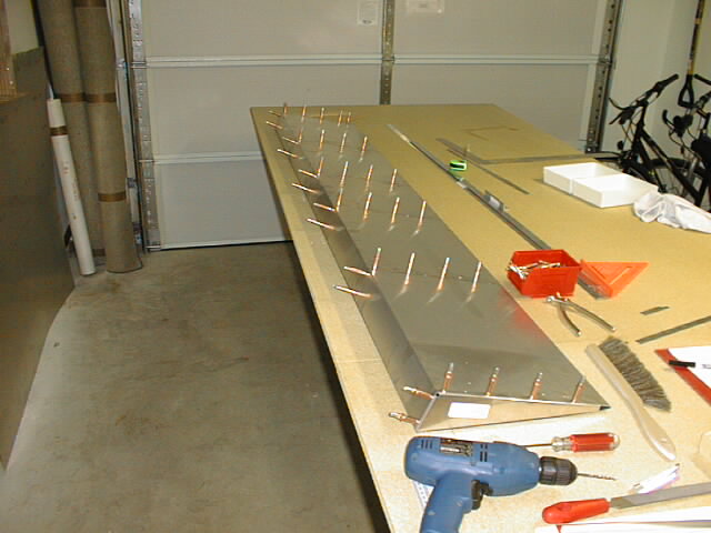
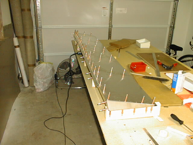
 All holes drilled. Ready to rivet.
 Everything riveted....almost! I ran out of rivets with fourteen holes left! Oh well, I'll get more.
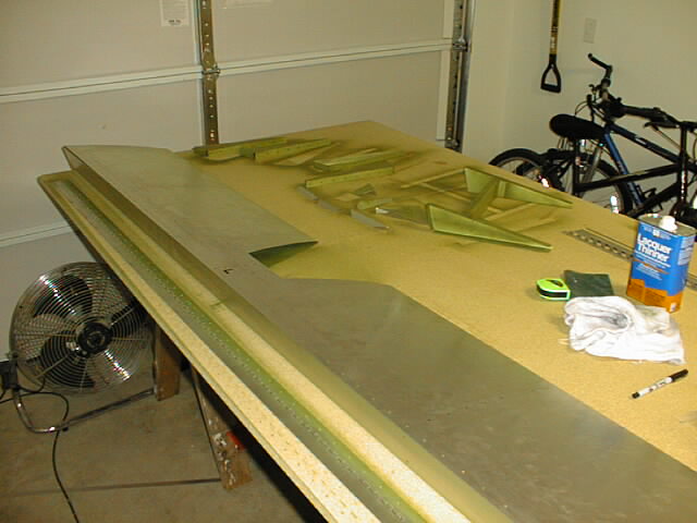
 Stabilizer and elevator re-hinged and hanging out of the way to make room for wing construction.
01-05 August 1999: Just a little more.....
 Lower stabilizer skin cut for front attachments.
 Skeleton traced on inside of lower skin prior to pilot drilling holes.
 Lower skin drilled and taped into place on skeleton. Rivet line on rear spar drilled with #30 and cleco'd.
 Lower stabilizer skin completely drilled with #30. Ready to deburr and prime prior to riveting to skeleton.
 Lower stabilizer skin deburred and primed with zinc oxide primer.
 Riveting lower stabilizer skin.
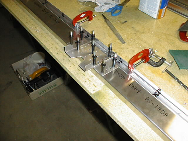
 This photo shows the slight "bow" in the spar rivet line. This is caused by all of the stabilizer ribs being the same length, but the spar doublers only extending partway out. this bends the outboard ends of the spars slightly together. The only solution is to shim the end flanges of the ribs, or just move the rivet line as I did.
 Building an airplane in your garage always seems to attract the neighborhood kids....
 And sometimes they can be a bit unruly!! :^)
27, 31 July 1999: Halfway there....
 Stabilizer parts.
 Rear attachment (6T2-3) shaped and drilled.
 Drilling the rear spar doublers.
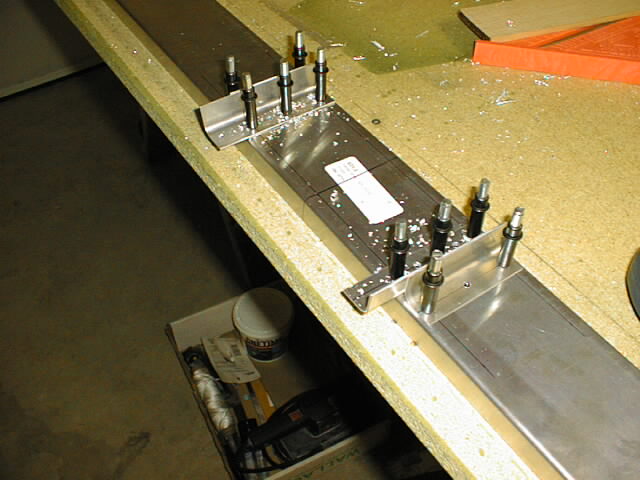 Drilling the front spar doublers.
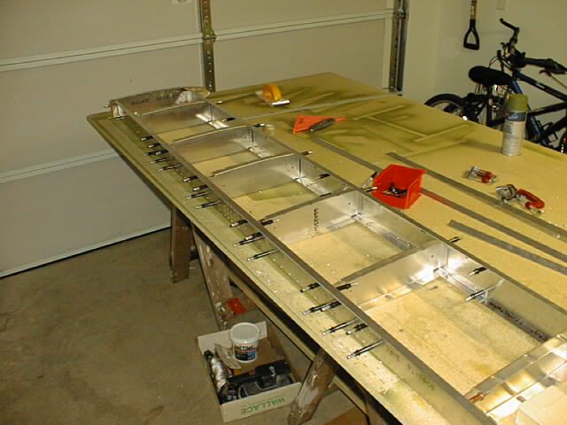 Trial fit of the stabilizer skeleton.
 All internal stabilizerparts drilled, deburred and ready to prime with zinc oxide primer.
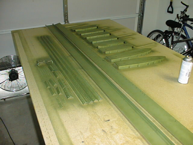 All primed.
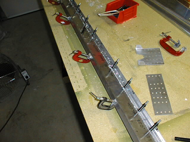
 Rear spar assembly riveted.
 Riveting front spar assembly.
 Riveting the ribs in place.
 Completed stabilizer skeleton. In case anyone is wondering, there are 178 A5 rivets and 44 A4 rivets in the skeleton. This was riveted in just over one hour using the hand-riveter shown in the photos . The A5's are much more difficult to pull than the A4's. Yes, my hands were tired. :^)
 Horizontal tail and elevator kit sitting on the workbench. Liz's Mustang GT convertible sitting outside the door. :^)
 Center rib assembly. Note the lack of primer. This assembly was taken apart, primed and re-assembled after this photo was taken.
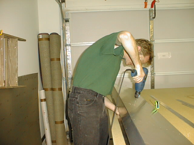 That's me drilling the elevator skin.
 Elevator skin with front flanges of ribs drilled and cleco'd.
 Elevator skin with bottom holes drilled and cleco'd.
 Hole for horn doubler (6T3-6).
 Elevator top skin and hinge drilled and cleco'd. Looks good at this point, and I felt good about getting it done without any errors....[play ominous music here]
 Now this is what you call an "oops". Note the nice 10mm edge distance for the rivet line on the elevator skin, and note the insufficient edge distance on the hinge. I was not a happy camper. However, the mistake was not terminal. $12 paid to Aircraft Spruce procured a dandy 2" wide hinge (the factory-supplied hinge is 1.5") that allowed me to have sufficient edge distance on both the skin and the hinge. Problem solved.
 All internal elevator components (including the skin) primed with Zinc Oxide spray.
 Riveting the elevator.
 Elevator complete except for trim tab.

![]()