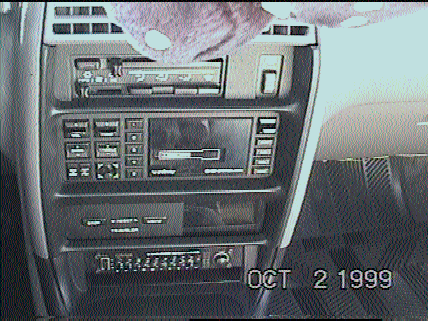
Lebaron Traveler Computer Installation
 Installing a traveler computer from a '90+ Lebaron into a '91+ Daytona is
easy as pie. The first step is probably the most difficult. It is finding a
trip computer. Daytona's never came with these computers or anything similar after
the 89 model year, but lebarons did. The pre-90 Lebarons and Daytona's are easy to
find and a good percentage of them have trip computers. But, they won't fit
perfectly in the newer dash of the '90+ Lebaron/ and Daytona's. You can,
however, fabricate your own mounting techniques. I'm not sure if the wiring is the
same in them either. Make it easy and locate one from a '90+ lebaron. And if
it comes from a junk yard, hopefully it works. Mine was in a '90 lebaron
convertible, top down, sitting in the yard for a year. Works great though.
Lets get on with the wiring. If you find a computer out of junk yard, remember to
also get the wire connector. Just clip the wires so you have plenty of extra wire to
solder new ones to. You will not find this connector in Daytona's. All
Lebaron coupes and convertibles already have the wiring harness behind the dash, so
you just plug the computer into it, mount the computer, and you're set to go.
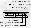
The connector looks something like this: Note that the pin numbers are labeled
along with the color of the wires.

Pin 1 goes to an ignition power source (power when ignition key
is on). I wired this to the defroster switch power source. Use a voltmeter to
determine which wire behind the defroster switch is the ignition power.
Pin 2 is ground. This can go to any metal surface on the
car.
Pin 3 is for the illumination. Again, the wires behind
defroster switch is an excellent source of power. And, again, use a voltmeter to
make sure you use the right wire.
Pin 4 is not used for anything.
Pin 5 will not be used either.
Pin 6 is the positive data bus. In a nutshell, the data
bus is the source of the information it needs to compute its functions. The traveler
computer recognizes electrical impulses from this wire, and turns it into data you and me
can read on the display. This wire is a little tricky to hook up. It goes to
the body computer of the car, which is behind the front passenger kick panel (behind the
panel to the right of where the front passenger's feet would be).
On the body computer, there are 2 large connectors on it.. a black one and a grey one.
We will only deal with the BLACK connector. If you look closely on the
connector, you will see tiny numbers on it where the wire enters the connector. You
want to remove some insulation from the wire labeled #7, and connect Pin 3 from the
traveler computer to wire #7 on the body computer. I do not recommend clipping this
wire... just remove some insulation off of it, so you can solder a wire to it.
Pin 7 is the negative data bus. It also goes to the black
connector on the body computer. This one goes to wire #20. Perform the same
procedure as above to connect this wire.
When you're done, when the key is turned to the run position, the display should come
to life. If nothing happens, wait awhile because as long as pin 1 and 2 are properly
hooked up, you should get a message on the display which says "F1-1" after about
10 seconds or so. This means the computer works, but the data bus probably isn't
hooked up right. Before installing the computer, I recommend to give power to pin 1
(positive) and pin 2 (negative) and see if anything pops up on the display. It takes
awhile for that F1-1 error message to show up, so give it about 10 seconds or so. If
nothing shows up, I would assume the computer is dead, toast, fucked, you get the idea.
 Installing a traveler computer from a '90+ Lebaron into a '91+ Daytona is
easy as pie. The first step is probably the most difficult. It is finding a
trip computer. Daytona's never came with these computers or anything similar after
the 89 model year, but lebarons did. The pre-90 Lebarons and Daytona's are easy to
find and a good percentage of them have trip computers. But, they won't fit
perfectly in the newer dash of the '90+ Lebaron/ and Daytona's. You can,
however, fabricate your own mounting techniques. I'm not sure if the wiring is the
same in them either. Make it easy and locate one from a '90+ lebaron. And if
it comes from a junk yard, hopefully it works. Mine was in a '90 lebaron
convertible, top down, sitting in the yard for a year. Works great though.