

Abstract
For our final project we decided to analyze an aluminum springboard. In particular, we decided to use Duraflex® springboards which have been used exclusively in ten consecutive Olympics from Rome to Atlanta and are used in international competitions around the world. Our interest in this project stems from the recent Olympic events which took place at the Georgia Tech Aquatic Center.
During the assembly period of our project, Anh Nguyen and myself, Theron Nix, took it upon ourselves to visit the Georgia Tech Aquatic Center to look at the boards first hand and make measurements accordingly. After our initial meeting, Anh decided to contact the manufacturer, Duraflex®, in order to obtain detailed schematics. A couple of weeks passed and Anh received a brochure detailing some of the specifications of our springboard. Anh Nguyen began the first modeling procedure by modeling the diving board and the associated components. Theron began work on the springboard stand assembly which consisted of the ladder and guard rails.
After the completion of the assembly Anh took both of our assemblies
and made a complete assembly of our components. We then performed
an FEM analysis on the diving board. We also took a copy of the
finished assembly and made an animation detailing the adjustable
fulcrum area.
Object Modeling and Assembly
Our Duraflex® Springboard assembly consisted of 27 unique parts which will be explained and detailed here. The Complete assembly consisted of 3 separate assemblies, Diving Board, Diving Board Stand and the Fulcrum. In order to orient the reader we have included a overview of the completed springboard assembly below in Figure 1.

Figure1. Overview of Springboard Assembly
Diving Board Assembly- Designed
by Anh Nguyen
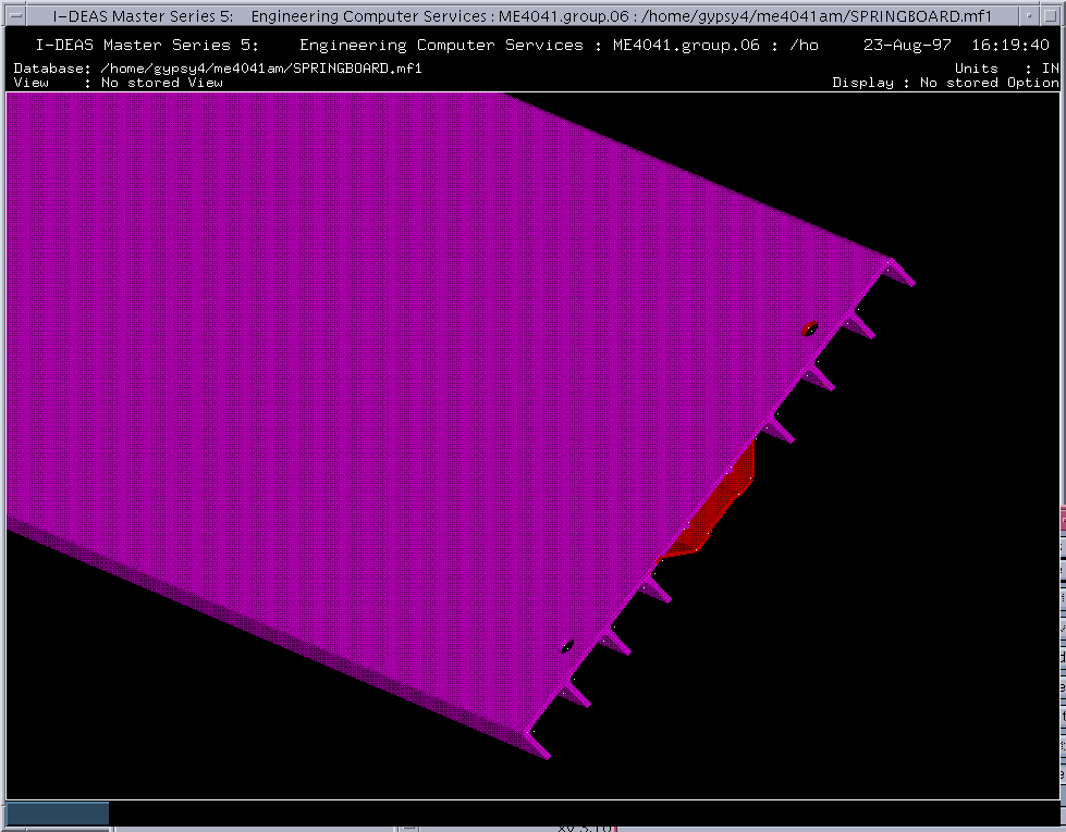
Figure 2. Cross Section of Ribbed Extrusion &
Torsion Member

Figure 3. Anchor End Cap
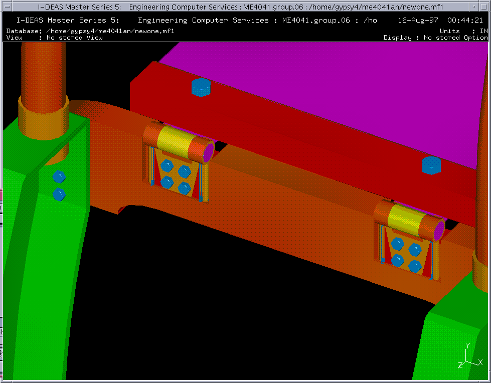
Diving Board Stand Assembly- Designed
by Theron J. Nix

Figure5. Diving Board Stand Assembly
Fulcrum Assembly- Designed
by Anh Nguyen & Theron J. Nix

Figure 6. Fulcrum Assembly
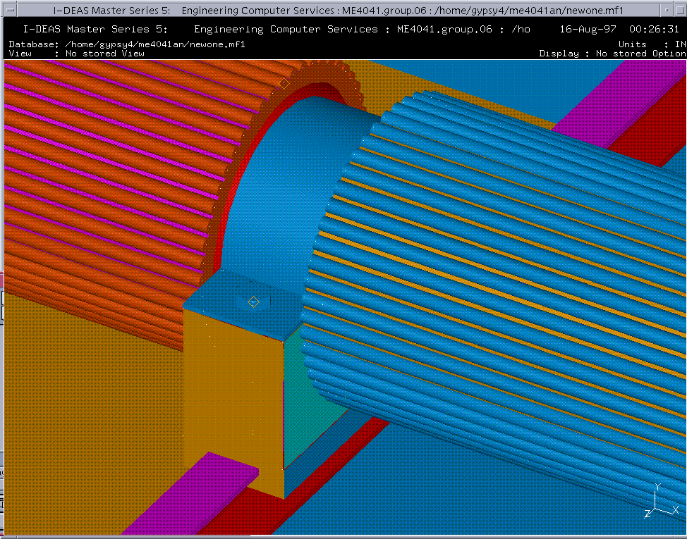
Figure 7. Close-up of Rollerblock
ASSEMBLY
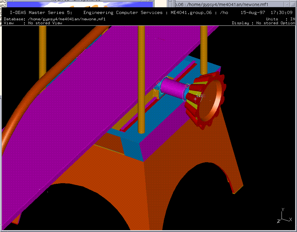
Assemblies are employed to visualize the completed assembly of all parts and animate the configurations of the assembly. Assemblies were performed upon completeness of modeling all parts, and they could be achieved in the Master Assembly Task. Our design is composed of 27 different parts and 20 bolts and nuts, so we need to assemble all the parts together. First of all, we had to create a parent hierarchy (Board Hierarchy) where all the parts were stored for assembly. We used basic commands such as Move, Rotate, Join, and Constraint Instances (Grounded, Face to Face, and Line to Line) for the assemblies, and permanent relationships between components were created by using the constraint function. Many connections were bolted, and the following list shows orders of the assemblies:
Board Hierarchy
Board
Fulcrum
Finite Element Analysis
Finite Element Analysis (FEA) was focused on the linear statics of the diving board. It was interesting to find a maximum stress and a displacement when the board was under a given load. Consequently, the safety factor was determined based on the maximum stress. The board has the dimensions of 16 feet long, 20 inches wide, and 3/16 of an inch thickness, and it is made of aluminum alloy (6070-T6), heat treated for a minimum yield strength of 50,000psi.
We first started to use solid elements for the FEA, but this did not work since the board is very long and thin. It went up to 100,000 nodes, and Ideas never finished generating all nodes and elements. We then decided to change to another method, two dimensional thin-shelled elements. It was crucial that the thickness of the board be provided when thin-shelled elements are employed; otherwise it would produce incorrect results.
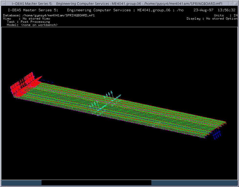
We also employed rectangular elements with the element length of one (1). This produced an FEM model with 6948 nodes and 6720 elements (See Figure 9). We also specified three boundary conditions for the model. The first boundary was set at the hinged end of the Springboard. At this end, the board has no translation in any direction and no rotation in X and Z axis. It, however, freely rotates around the pin of the hinge (Y-axis). Another boundary was restrained and located at about 80 inches from the hinged end (fulcrum). At the fulcrum, the board is not able to move in any direction, but it is free to rotate in all directions. Note that rotation here means the board is not very tightly fixed. The third boundary was the load at the front end of the board. The average weight of a diver is about 120-200 lb., but the Springboard is unlikely to fail at this range of load. Thus, for the purpose of analysis, we decided to use 300 pounds concentrated load at the diving end (see Figure 10).
Under an applied load of 300lb., the Springboard bent and underwent
the highest compressive stress at the fulcrum. The Springboard
also deflected a distance of 5.03 inches under this load. In addition,
the highest stresses was about 37,800 psi that produces a safety
factor of 1.3.

Furthermore, we experimented with some other FEMs to make sure
that the results were consistent. First, we kept everything constant,
but moved the position of the fulcrum closer to the diving end.
The result was very intuitive; both the displacement and the maximum
stress were lower than the former case. Secondly, the same procedure
was applied, but the fulcrum position was moved farther from the
diving end. In this case, the maximum stress and deflection were
higher than the previous cases as was expected. Finally, we kept
all the boundary conditions constant as the very first situation
except for the load that was increased to 600 pounds. In this
case, the displacement was 9.84 inches, and the maximum stress
was 74,800 psi which is higher than the minimum strength of the
aluminum alloy (50,000 psi), shown in Figure 11. Therefore, the
Springboard would fail at this load.

It is noted that the FEA just focused on the diving board itself.
However, there is an Torsion Member Extrusion riveted under the
board. This piece would significantly increase the stiffness of
the board. Therefore, the Springboard will not break at 600 pounds
as previously described, but it is much stronger and stiffer due
to the support of the Torsion Member Extrusion.
Conclusions
In our computer design and analysis of an aluminum Duraflex® Springboard we were involved in three major tasks using the Ideas software. First we had to model the objects that we wanted to assembly using the Master Modeler application of the software. Most parts were created using the specifications from the Duraflex® manufacturer at a 1 to 1 scale. From this point we made several assemblies using the Master Assembly application. We made a parent hierarchy named, "Board Hierarchy", where we placed all the parts for the assembly. We then used basic commands such as Move, Rotate, Join, and Constraint Instances for the assemblies. Once the assembly was complete and constrained, we then made a number of configurations of the assembly at different positions and angles to make an animation of the moving Fulcrum Roller. An FEM was performed on the springboard to analyze the linear statics of the board. During these steps we discovered many advantages and disadvantages within the Ideas software package.
The Ideas software package is a powerful engineering graphics tool and is relatively simple to use and learn in a short period of time. The main advantage over other modeling packages is the ability to visualize the object at any perspective with a touch of a button. This allows the designer to more easily shape and model an object. Another feature which was very desirable was the application's interface. The interface was arranged so that all the necessary buttons were within reach at any given time. The main drawback to the application was it's inability to undo changes easily once a object was modified. Although there was a history button that allowed the user to go back through the steps, it would be nice to just hit undo and have everything go back to the way it was. It is good advice to save work more frequently to ensure that the project is not lost. We also encountered many problems during our FEM analysis.
Since our FEM had a large number of elements (a huge matrix formed), we encountered many problems for obtaining the solution. We ran out of limited disk space, and the system was very slow because FEM took up a lot of memory. We were unable to obtain any solution even though we spent a lot of time. Later on, we decided to run the solution by using the Temporary and Batch file ,see instructions from the ME4041 web page. The advantages of this method are that it doesn't require a lot of disk space and sends an email message to inform us when the solution is complete. It's only drawback is that the FEM file that is created will be lost when the workstation is rebooted due to the fact that the file isn't in our directory.
Our advice to the future users is that they begin the project
as soon as possible. This is necessary because the system is slow
due to the number of students using the software at a given time.
Another helpful word of advice is that during the FEM analysis
the user should use 2-D thin-shelled elements, this helps when
you have a huge object to analyze.

