Red-Header
The header will be a stainless large tube log
type.
The primary tubes will be 1-7/8".
I completed this header in about 2 weeks working
on it in my spare time.
The header will be for sale when completed, or I
can build a header to suit your custom
application.
Expected increase over stock (15-20 psi) manifold will be 30-50HP.
Expected increase over stock (20 psi or less) with Turbonetics Stage3
turbine shaft and housing is 50-100HP.
Cost on the header is $500+
Lets get started!
Step 1
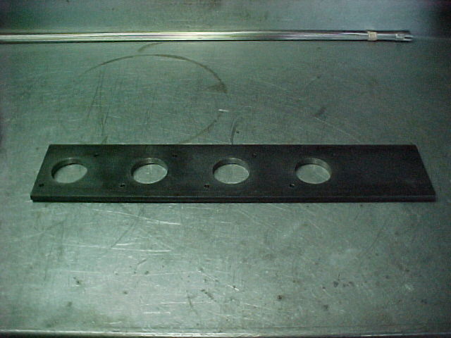
Header flange kit
The large tube design requires a header flange
kit that relocates the header stud locations. All
other kits use the stock bolt locaton that limits
max primary tube size to 1-5/8" (this size is
pinched at the bolt locations). The flange kit I
sell for the DIY's will accept up to 2-1/8"
primarys
(w/o being pinched).
The header port flange/s will be supplied with he pilot hole in correct location to use a hole saw to cut the center out for the primary tube to be inserted and welded (your choice on size).
The new stud locations can be done with a drill press, and basic measuring
equipment.
The kit is supplied with a transfer plate to give
you the proper locations for the new stud holes.
You will want to start with a junk or "dummy
head". This will allow you to goof, and not ruin
your "good" head. The "dummy heaed" will be used
as a building aid throughout the building/welding
of the header.
It is time to locate the new stud locations on
your dummy head. Start by bolting the transfer
plate to the head by the 2 bolt holes that line
up with the stock bolt locations. Then use a 1/4"
transfer punch to mark your new locations on the
head. Once this is done, remove the plate, and
store for later use.
The head can now be drilled and tapped for the
new studs.
The top 4 will be drilled to a depth of 1/2".
The lower 4 will be drilled through the head face into
the water jacket.
You will need a 3 piece tap set for the top 4 to
get full thread depth. The top 4 are blind holes
and need to be bottom tapped.
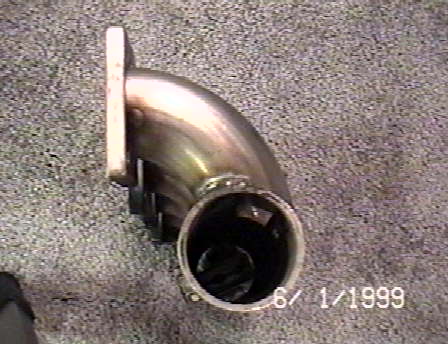
The turbo mount flange will be for a Ford t3 bolt
pattern (holes pre drilled for
a t4 optional).
The best plan for building on the dummy head will
be to use bolts to hold the port flange/s, because
studs get in the way during the welding
process.
The port flange/s MUST be tightened to the head
firmly before the welding begins to stop warpage.
It would be a good idea to use a large flat
bastard file to debur the exhaust face of the
head and flange/s to make certain that they will
bolt flush.
Any sealing imperfections now will be magnafied
after welding.
Step 2
Building the log, port flange/s, and elbows
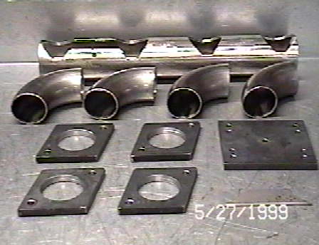
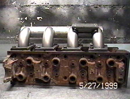
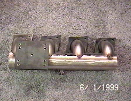
This is where the fun begins. The parts picture will show almost all the pieces to build the log header with.
At the top is the log.
It is a piece of 2.5"od, .125"wall stainless tubeing.
The holes in the flange/s were pilot marked using the transfer plate to locate them for equal spacing and uniformity, then drilled with a 1/4" bit to pilot the hole saw.
The main 4 holes in the log were drilled with a 1-7/8" holesaw in a normal drill press.
The holes were drilled off center to allow the log to rotate in toward the head for the proper clearance and turbo location.
It is now time to drill the center holes (1-7/8") in the port flange/s. You will use the same hole saw that was used when cutting on the log.
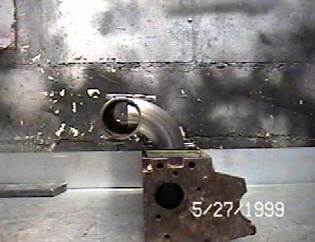
The 90* primary tube bends will take a little
measuring (to get a true 90) befor cutting. This
will insure that they sit in the port flange/s
correctly and enter the log at the correct
location/angle.
Step 3
Trial fitting
This is the stage of the prodject when the final shape starts to emerge.
By now you should have your port flange/s bolted
to the dummy head.
Place the 4 elbows into the port flange/s.
If they are a little loose, do not be
alarmed.
You can use an adjustable wrench to flare out the
end of the elbow to give a snug fit in the
flange/s.
Now you can slide the log onto the primaries to test the fit and adjust as needed (filing, grinding, tweeking, ect..) to make the log fit square and tight.
By now you are getting a feel for the shape and
ease of building this header.
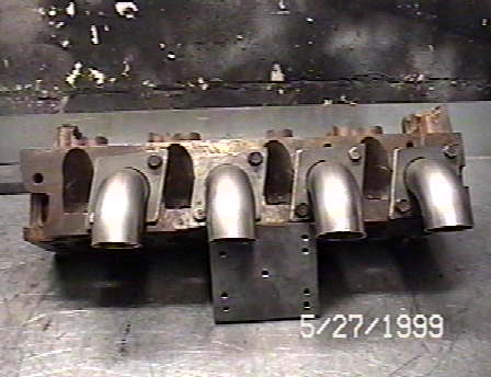
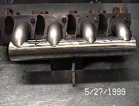
Here are a few picts of what you will be looking
at.
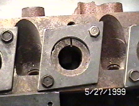
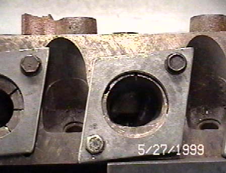
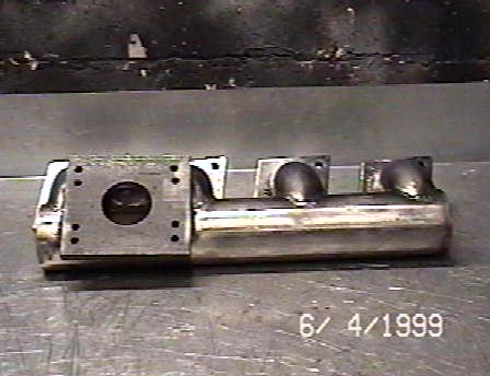
These next 2 are port flange/s in place and showing the actual view of the exit w/o the primary in the way. The first shows you a stock exhaust port in relation to the 1-7/8" tube. The second shows a "D-port" port matched to the 1-7/8" primary tube. HUGE is the word.
Step 4
Welding
This is the step where you need some welding skill/s, or know someone who does.
I use TIG welding for my headers, but MIG will also work.
You should have mocked up the header by now to see that all your parts fit tight w/o gaps.
Start with the primary tubes.
Assemble the log and primary tube section of the
header using the port flange/s that are boltedĀto
your head as a guide.
Then tack weld the primaries to the log on 3 points.
This wll allow them to hold position as you start your welding process on the tubes.
DO NOT TACK THE TUBES TO THE PORT FLANGE/S YET!!!
This header design requires the primaries be welded
to the log before being weldd to the port
flange/s.
To minimize the chance of warpage, I use the
lowest amp setting on the TIG, and work in short
welds.
The reason for welding the primarys to the
log first is, access to the head side junction of the log and primary tube. You can not get to this area once the tubes are welded to the port
flanges.
You will want to weld the head side half
of the primary then stop.
Do not weld the front of the primary tube to the log till the port flange/s are completely finish welded.
This will allow you to bolt the header back on the head to minimize warpage.
It is now time to tack the primaries to the port flange/s.
This should be done in 3 spots or more per flange.
Do all spots on all flanges before removing the header from the head. Again, to minimize the chance of warpage.
The port flanges will be welded to the primaries
from the head side of the flange.
Allen
Moore
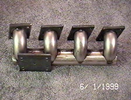
This next group of picts will show the near complete header with minor finish grinding to be done on the turbo mount flange.
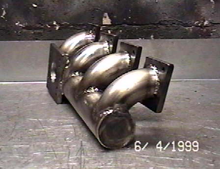
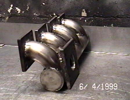
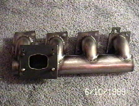
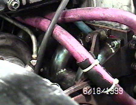
AT LAST!!!
Here is the finished product!!!
If you look close, you can see the SVO IC, ac compressor brackets and support, and the new bolt locations on the #1 primary flange.
If at any time you have questions about how I
build the header please feel free to e-mail me.
Lakeland, FL