Red-Header
The header will be a stainless large tube 4 into 1
type that relocates the turbo to the front of the engine.
The primary tubes will be 1-7/8".
The turbo mount flange will be for a Ford t3 bolt
pattern (t4 optional).
Expected increase over (15-20 psi of boost)stock manifold will be
30-50HP.
Expected increase over (20 psi or less) stock with Turbonetics Stage3
turbine shaft and housing 50-100hp.
Expecterd cost on the header, down pipe, and waste gate will be $1250+
Lets get started!
Step 1
Header flange kit

The large tube design requires a header flange
kit that relocates the header stud locations. All
other kits use the stock bolt locaton that limits
max primary tube size to 1-5/8" (this size is
pinched at the bolt locations). The flange kit I
sell for the DIY's will accept up to 2-1/8"
primaries
(w/o being pinched).
The header port flange/s will be supplied with the pilot hole in the correct location to use a hole saw to cut the center out for the primary tube to be inserted and welded (your choice on size).
The new stud locations can be done with a drill press, and basic measuring
equipment.
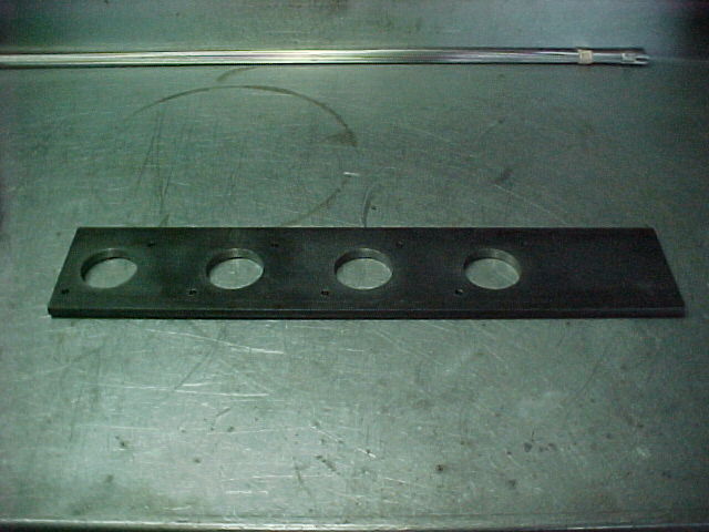
The kit is supplied with a transfer plate to give
you the proper locations for the new stud holes.
You will want to start with a junk or "dummy
head". This will allow you to goof, and not ruin
your "good" head. The "dummy heaed" will be used
as a building aid throughout the building/welding
of the header.
It is time to locate the new stud locations on
your dummy head. Start by bolting the transfer
plate to the head by the 2 bolt holes that line
up with the stock bolt locations. Then use a 1/4"
transfer punch to mark your new locations on the
head. Once this is done, remove the plate, and
store for later use.
The head can now be drilled and tapped for the
new studs.
The top 4 will be drilled to a depth of 1/2".
The lower 4 will be drilled through the head face into
the water jacket.
You will need a 3 piece tap set for the top four holes to
get full thread depth. The top 4 are blind holes
and need to be bottom tapped.
The best plan for building on the dummy head will
be to use bolts to hold the port flange/s, because
studs get in the way during the welding
process.
The port flange/s MUST be tightened to the head
firmly before the welding begins to stop warpage.
It would be a good idea to use a large flat
bastard file to debur the exhaust face of the
head and flange/s to make certain that they will
bolt flush.
Any sealing imperfections now will be magnafied
after welding.
Step 2
Building the primary tubes

Here you can see most of the materials it'll take to build the header.

I will use tape to hold the tubes in position to spot weld, then use a vise to hold the tube steady while welding the joint.

While fitting the primary tubes, and getting the routing, pay close attention that the tubes run parallel with each other to keep the header looking "professional".

More fitting...
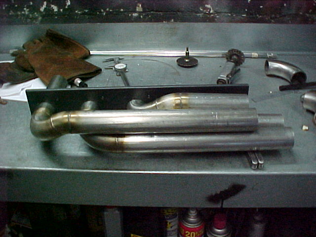
This shot shows the 4 primary tubes NEAR completion. Yes this was the HARDEST part of the whole job.

This is the port flange, collector back plate, and turbine mounting flange in ready to weld form...the three oval cut-outs are for spark plug access.


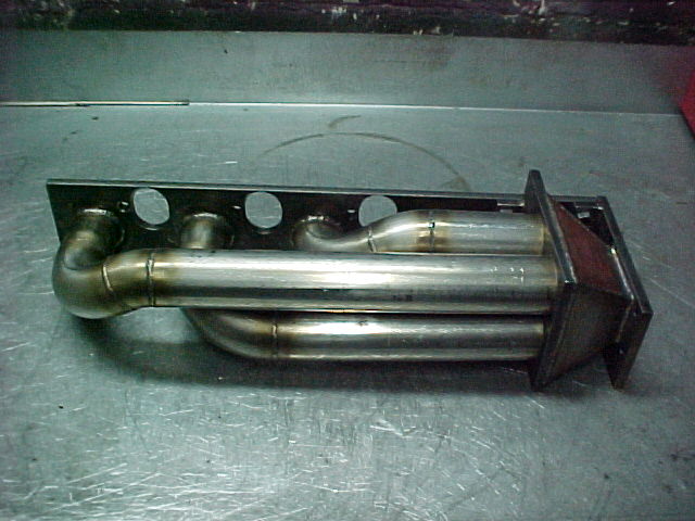
These shots will start to give you the shape of the finished header...
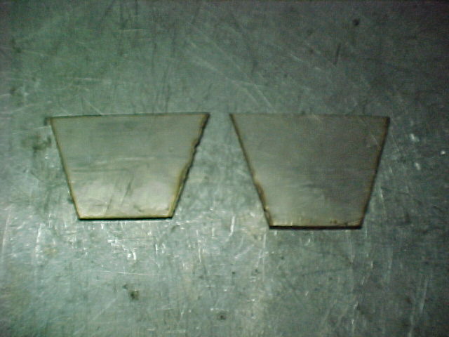
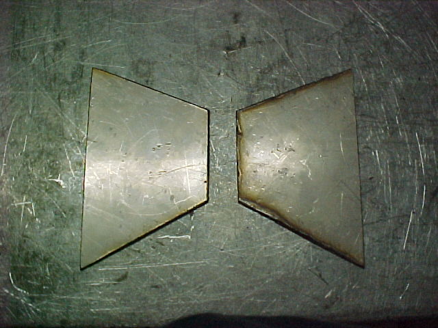
These are the pieces that will be welded between the collector back plate and the turbine mounting flange to make the complete collector box...

This is a view of the collector with the top plate tacked into position...

This is a view of the collector with the bottom plate tacked into position...

This is what the collector box looks like befor the side plates are attached.


If at any time you have questions about how I build the header, or question on why, please feel free to e-mail me.
Allen Moore
Lakeland, FL