Draft of autonomously powered lifter
I guess many remember that in my recent calculations of the
specs under which lifter can be self-powered (lifting its own power-
supply) there was a parameter max_dens for a maximal density of
collector/corona wire array per meter. Who don't know what I am
speaking about, take a look at "Complete engineering model of autonomously
powered
corona-discharge propelled aircraft" section at
http://sudy_zhenja.tripod.com/lifter_theory.
Anyway, the calculations for Savioiur-type power supply gave value
of max_dens~ 0.3 gm/m and I thought this value quite difficult to
achieve. However, today I got my hands on a piece of an Al vapor-
deposited mylar film used in winded capacitors. This is incredably
light and strong, and its conductivity is quite high (1 cm distance
contact gives ~10 Ohm). Now, its area specific density is
0.6 mg / cm^2. This means that 1 m of 1 cm wide stripe of such a film
will weigh 0.063 gm ! This is twice better then the max_dens
caclulated.
Remembering that 50-gauge corona wire weights almost nothing, we can
see that 50 gauge wire/ mylar Al-plated collector combination can
satisfy self-powered lifter density requirement quite easily. This
film is also widely available - any dry winded capacitor (low voltage
one) would have 100 m of it, and they are very cheap.
I looked more closely on possible design based on Al-coated mylar
collector. The design could be like this (Exact dimension
calculations depending on voltage and particular electrode density
can be made with MathCad worksheet you can download from my site,
http://sudy_zhenja.tripod.com/lifter_theory):
- Electrode array lenght L= 800 m
- Saviour power supply with Li-ion batteries (~600 gm, 50 kV, 150 W)
- collector is made from twisted to tube-form 1cm wide Mylar Al-
coated film from condensors
- Corona/collector distance 70 cm
- Corona/collector couple arrays have distance between each other 10
cm (total area would be 8m x 8m if flat)
- Corona/collector arrays are stacked, 8 arrays one above another.
This reduces the base cross-section to 3m x 3m, and hight of the
device is 6 m.
I belive to privide the lightest possible frame and more easy handwork,
it is useful to employ stressed barrel configuration.
To visualise this idea more clearly, I made a draft drawing (click
on picure to increase)

Anyway, in the beginning some smaller prototype could be build which
would test the main design parameters:
- the twisted as spiral to tube-form 1cm wide Al-coated mylar film
as collector
- 70 cm distance between electrodes
- 50 gauge wire
To clarify the idea additionaly, I add here my answers to the questions about this design, asked by Rolland:
>1. As I understand the design you are proposing, the "basic" lifter
>element is a AL coated mylar tube with a circumference of 1 cm and
a
>length of 3 meters. Thus the tube diameter would be 1/Pi cm or
>approximately .32 cm. Correct?.
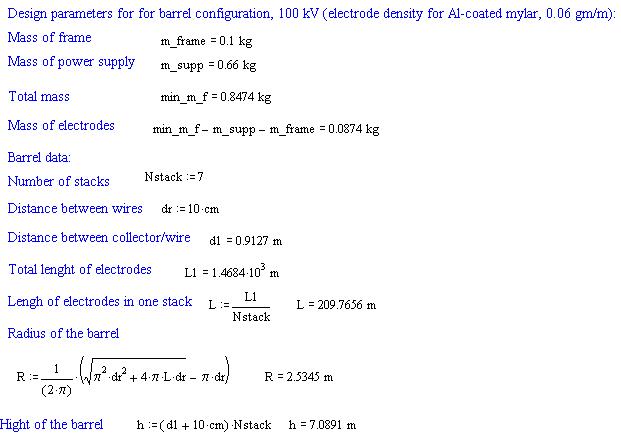
If we use circular (barrel) design rather then square design, one stack
(or layer)
will include several wire/collector circles with different diameters.
The lengh of each circle will be
L[i]=2*pi*(R-dr*i) where R is the biggest radius, dr - distance between
wires 10 cm, and i=0..ceil(R/dr)
The largest radius can be approximately found from summar lengh
L of all circles in a stack as
![]()
The L should be found as Ltot/Nstack. I found that for Ltot 900m the
Nstack = 7
(seven stacks) gives radius ~2 m with hight 5.7 m.
>2. A series of these tubes (around 31 of them) would be "laid"
>parallel to each other and approximately 10 cm apart (measured from
>the centers of adjacent tubes). This then forms the "bottom" square
>of our 3m by 3m by 6 m lifter. Is this correct?
Yes, in square case. For barrel case see above.
>3. At 70 cm above these parallel tubes would run 31 parallel 50 gage
>steel wires, one wire above each tube. Is this correct?
>
>4. At some distance above the steel wires, (presumably greater than
>70 cm ?) , we would start over again with 31 parallel tubes oriented
>in the same direction as the bottom layer and above them at 70 cm
the
>31 wires. Is this correct?
I believe that the best configuration would be with exchanging wire/collectro
polarity, like this
(from the top):
- wire +
- 70 cm distance
-collector (-)
- 10 cm distnce
- wire (-)
- 70 cm distance
- collector (+)
- 10 cm distnce
- wire (+)
... so on.
Saviour already tested similar stacking, In his case the corona-wire
for next level was replaced by sharp edge of
foil- collector from "upper" level. I put a actual wire of same polarity
10 cm below the collector because
our collector is made as at tube to prevent counter-current, and so
has no sharp edges.
>I am sure I have missed something, because to get 8 such layers, I
>would come out with a total height greater than 6 meters. Maybe you
>can clarify.
h= Nstack*(10cm+70cm)
For barrel configuration h = 5.6 m
>How do you propose to maintain the shape of the mylar tubes? Are
>they wrapped around a tubular core (Styrofoam? , Aerogel?) or around
>a hollow straw-like plastic tube? I think they have to be very rigid
>over a 3 meter length. Is this correct?
For barrel configuration the mylar tybe will be in contact with "guiding
tehters" at quite small intervals.
I think they can be glued to the tethers at contact points with acryle
instant glue. As for supporting the tubular form of twisted
Al-coated mylar film - I believe it can be avoided. First, the mylar
film is quire rigid, and holds tube form
if 1 cm wide stripe is twisted. At the other hand, when we switch ON
high-voltage, electrostatic repulsion will
foce the stripe surfaces to be as far as possible from each other,
so forcing it to take tube form.
>If so, have you worked out
>the weight, so we have a reasonable idea what one tube with its
>internal "supporting element" and one "corona" wire would actually
>weigh?
We have some free space for additional "pay-load" such as frame, because
the Al-mylar is
way under-critical (0.06 gm/m vs max_dens=0.3 gm/m). Calculation shows
that maximal payload (additional to 0.66 kg
Saviour power-supply) which lifter with 0.06 gm/m electrode density
can carry at V=100kV is 0.367 kg - so that is the maximal weight of the
frame we can afford. In this (worst) case of heaviest possible frame
we will have electrode lengh 8.7 km. So I guess we need to do
much better then 367 gm frame. For further calcs I will assume 100
gm.
But how light we can actually make the fram depends on material
and design. It needs some experiment to find out
fram dencity per volume before I can put this numbers into calculation.
I believe we can use very thin nylon silk-cloth tubes (~0.5 cm diamter)
impregnated by epoxy as light composite material for frame, and
thin nylon silk thread as guiding teathers.
>Have you tried to work out an estimated total weight of the lifter
>with power supply, even with "best case" assumptions regarding tube
>weights and the weight of a minimal supporting structure?
If I assume that whole frame and threads weigh together 100 gm (payload),
the resulting design parameters
are like this (calculated for 100kV):
Note that adding additionoal payload gives a need to increase efficiency,
as power supply is not changed.
Therefor d1 increased from 70 cm without payload to 90 cm with payload.
Now, same caculations for 50kv case:

As you can see, the electrode lengh increases at lower voltage, but
total hight can be significantly
reduced - which means that at lower voltage we have higher volumetric
force
density, which might in turn allow to use lighter frame (frame density
is volume related).
>Are you of the opinion that a series of lifter elements would generate
>about the same amount of lift if they were either run side by side
or
>if they were "stacked" one on top of another (at some appropriate
>spacing). That is, does lifting power just ADD as the number of
>elements increases no matter how they are oriented?
Mostly I think it just adds. Saviour recently mentioned good idea that
with pressure
k decreases, so efficiency ef=d/(k*V) could increase if higher stacks
increase pressure
for lower stacks. However, my equations assume that air is not moving.
For high wind rates, comparable with
ion velocity (~300m/sec) all equaitons are no longer valid (ion flight
time between electrodes will become shorter)
so such simple logic might not work and more exact calcs considering
air velocity are needed.
>I agree that using your ideas, we could proceed in a step-by-step
>fashion, measuring and testing at each phase. First build a single
>tube or partial tube element and measure results, then a series,
>(maybe 5 or so) then a small stacked array, etc.
Yes, and also testing of + -- ++ -- stacking would be interesting.
Regards,
Evgenij