Evgenij Barsoukov
In resent year everybody got used to the idea that Lifter efficiency can be increased by using larger corona-collector distance. That however comes with the price of very small force per unit length. Simply speaking, if you take usual Lifter and just increase the distance, you will hardly notice any force. Power consumption will be even smaller, but who really cares except for Lifter with on-board power supply which anyway does not exist yet.
However, there is other way to improve efficiency without sacrificing
force. Indeed, in multi-staged lifter every stage is first producing ions
on corona-wire, then consuming (neutralizing) it on collector, then again
producing/consuming same ions at each of the next stages. Ion production
does not come free it cost energy which is uselessly wasted at each stage.
Moreover, ion production has other unpleasant consequence for efficiency.
While created force (what we wont) is proportional to current and distance,
used energy is proportional to field intensity E, current and distance.
That means that areas between electrodes with high E are wasting a lot
of more energy then areas with low E while producing same thrust as low
E-areas as current is same for both. To create ions we need areas with
high E and are forced to lose most of energy there.
Why not reuse ions from previous stages? This idea surfaced in our discussion with Saviour about my proposal on 3-electrode design. Indeed, we could produce ions in ionizing stage, and after that keep pushing them through all other stages without neutralizing them. To achieve that we play cat-and-mouse with ion cloud. Each time when it is almost reached collector, we set collectors voltage at zero so ions can not be neutralized. But we move attracting charge the next electrode, so ions still are attracted forwards. This can be repeated indefinitely without need to ever re-create ions. Whats more, we would need energy-wasting high-E areas only in first (ionizing) stage, while in all other stages ions will always stay in efficient low-E areas.
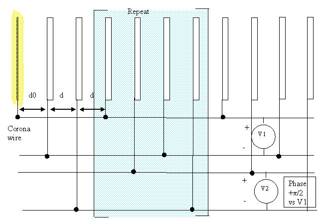
In lest couple of month I created a simulator (Mathcad program) where I could observe behavior of ion cloud in a field of multiple wire-electrodes and try different electrode configurations and voltage profiles which would achieve realization of above idea. Finally I succeeded! A simple electrode configuration, two AC-power supplies running with ?/2 phase shift to each other turned out to be able to do the trick. AC-frequency is adapted so that ion cloud passes a stage in same time as peak voltage passes from one electrode to another, and therefore cloud never catches voltage-wave. Figure 1 shows electrode configuration and electric connections realizing this feat.
Figure 1 Electrode configuration for providing ion cloud gliding from corona-wire (corona shown as yellow) through the array. AC peak voltage should not exceed V0/2 to prevent ionization outside + - ?/6 from peak (V0 is corona onset voltage). Ions generated outside this phase area will not propagate forwards. Note that first stage is different and consist of only 3 electrodes.
Setup employs two voltage sources operating at the same frequency. Frequency is selected so that ion cloud moving with the field equal to minimal field between two electrodes would reach then next electrode during one period (details below). Phase shift pi/2 between 2 voltage sources guaranties that when ion cloud reaches next electrode, voltage on it is zero.
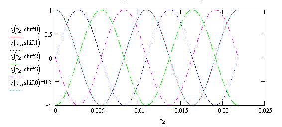
Figure 2 Voltges on subsequent electrodes
To clarify what happens between electrodes, below is the Figure 3 showing
the field change and field-induced movement of ion cloud with time. As
can be seen, ion cloud is always kept in a positive (forward-moving) field,
what results in its continuous movement forwards.
Details of the calculations is given in separate
article . There is also a mathcad file
which allows to make
all the calculations in this article by yourself, if you use MathCad
viewer (see toolbox).
Below I avoid complex explanations, just give here simple recommendations
how to set up a working prototype.
1. Distance between electrodes, d=3cm
2. Distance between first (ionizing) and next electrode is d*1.16
3. The last electrode should be added to capture all ions. It should
be out of phase with previous section.
I found in my calculations that placing electrode connected as
second electrode in each section does a good job capturing
4. Frequency of voltage sources is optimized for this configuration as 90 Hz
5. AC Peak voltage V is equal to V0*2, where V0 is corona onset voltage.
In this
case (with r=0.1mm) V0=7 kV Voltage can be less but can not be more
then V0*2 otherwise some of generated ions will be reflected backwards.
V0*2 provides +-?/6
window near peak where ions are generated.
Because my calculations do not take into consideration space charge, they are valid only for very small currents. For high current manual tweaking of frequency and d0 might be needed. Here is how:
- Connect oscilloscope to a sense resistor sensing current going into
the last (most far from corona wire) electrode.
- Switch ON both power supplies, change frequency on both on them so
that peak current through the last electrode is maximized. Current is maximized
if ion cloud is in the interval between electrodes (it increases effective
capacity of the gap). So if frequency is correct and ion cloud reaches
last electrode, AC current through it will increase.
- If no current increase could be achieved on the last electrode, move
nearer to the corona wire, as ion-losses might prevent cloud from reaching
electrodes.
- Once frequency is optimized, current can be further increased by
modifying distance d0 between corona wire and first electrode (usually
a little larger then other electrodes). Optimal distance in first gap is
different because field in first gap differs from other due to ionization
losses.
After these manipulations ion cloud should reach the last electrode
and do so in every cycle. Both negative and positive clouds will go through.
What did we achieved this way, how much better efficiency can we expect?
Power usage can be calculated by integrating the E which ion cloud experiences
on its way, and multiplying it by current. Because E is high only on first
electrode (wire), integral in all other electrode gaps will be small.
Figure 4 shows potential which ion cloud experiences during its flight,
which supports this notion.

Figure 4 Potential experienced by ion cloud on its flight patch
My calculations based on integration of this E along the flight patch show 6.27 times decrease of the power consumption as compared with the case when we would have corona wires in each gap, without decrease of force. The increase of efficiency becomes greater with d and less with r, it can be estimated as
To summarize, we can increase efficiency greatly without sacrifysing
force that means more compact design and finaly ability to lift power
supply by a device of acceptable size. In fact my calculation shows that
self-powered lifter with radius of 0.4m and hight 1m will be able to lift
itself and 600gm power supply and 100 armature.