Enter the particular Lifter design parameters here:
Radius of corona wire
Radius of collector wire
Distance between corona wire and collector
Lenght of wire
Dielectric constant
Ion mobility
Used equations
E produced by single electrode with charge Q
Eqn 1
Corona onset voltage (which will clamp mono-polar
interval voltage between first 2 electrodes)
Capacity/meter of a 2-wires couple with wire radius R
Eqn 2
Derived from above, charge on a single wire when voltage V is applied
Eqn 3
Combining Eqns 1 and 3, and considering field inside electrodes as zero:
All wires
Eqn 4
First (corona) wire, using distance d0
Note that because of clamping (voltage on corona-wire surface can not exceed V0) V0 should be used to calculate charge on corona electrode regardless of actual voltage between electrodes
For example, field of two wires at a line going through their centers (field inside ignored)
Eqn 5
Frequency of field modulation should be such that during one period ions
fly over 4-electrode stack. We are trying to achieve that ion cloud will always be
on the "bottom" of above E-curve, so field is always equal to minimal value Emin.
At such field the movement velocity will be E*mob (mob - ion mobility coefficient)
Emin between two wires can be found from eqn 5 as
Eqn 6
This way the velocity is
Flight time between electrodes
Because one period should pass when cloud passes 4 electrodes, required
frequency is 1/tau*4
Because first electrode set is different from others and because field is not always equal to the "optimal" minimal field between electrodes, this frequency has to be further
corrected a litle. By optimizing this frequency manually to achieve minimal integral
E over flight period I came up with correction factor
Voltage signal in time domain is given as described below
To introduce frequency shift in each subsequent electrode, we can modify fi.
Fi is assigned a different shift value shift0,shift1 etc.
Below is shown periodicaly changing voltage for subsequent 5 electrodes
Here we create array showing positions of all electrodes, which will be used in
calculation of overal field
We are making array for 4 sets of electrodes, 4 electrodes in each set
All positions:
Below equation (Eqn 7) gives field of entire set of 16 electrodes, as linear combination
of field given by Eqn 4.
This is same equation written so that freq and Loc can be modified
For optimization purposes it is convenient to be able to change d0 and see how result
changes. Below function allows substituting d0 and results in same field equation
To calculate ion movement in this field we have to use itterative calculation, because
in any moment of time we need to know position of ion to know his field, in turn
needed to calculate its velocity v=E*mob
To solve this problem we assume that E is constant during small time steps, and
use calculated position after each step to calculate E for next step.
We can set initial value of x for time zero
to surface of corona wire
Results of this itterative calculation is below. As you can see, distance is increasing,
which means that ion cloud is moving forward.
Ion position change with time.
Field which ions experiences on its flyight patch
As you can see, ion cloud experiese quite low field most over its flight patch.
Because field near wire increases very fast, it still sometimes see relatively
high field near wires, despite the voltage on the wires decreasing rapidly as ion approaches. When ion touches the wires, voltage is always near zero. Even if
it is not equal to zero, amoun of charge on electrode is very small so it would not
neutralize too many ions.
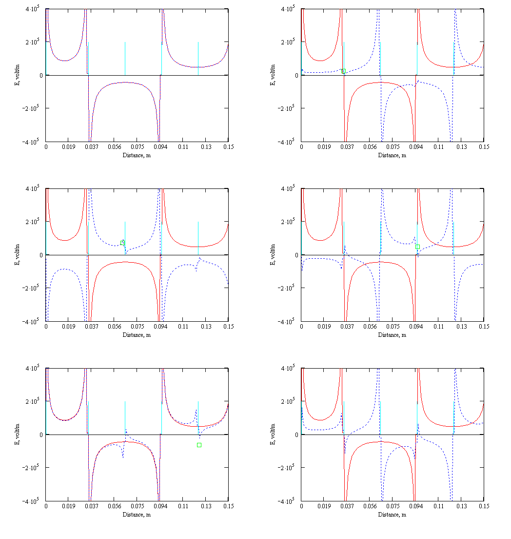
How the ions move can be further clarifed by simulation of entire field change with time. Set "tmove" to the time where you want to see the field and position of ion cloud, showed as green square.Enable assignment of "tmove" from FRAME variable to automatically change the position to animate cloud
gliding using "View-animate". After opening the Animate dialogue drag-select the graph
below and push "animate". Set max. value of animation variable to 50.
Blue lines indicate electrodes. Red line is field at time zero, and doted lines
is field at time "tmove". Increase tmove and see how field is changing and
how ion cloud (green dot) is moving forwards.
Summary:
Above results show that chosen configuration of electrodes, frequency and
distances result in continuous forward field experienced by positive and negative ion
clouds generated on first (corona) electrode.
Ion cloud never "touches" electrode with substantial charge on it, as voltage on each
electrode approaches zero as ion cloud is nearing it.
Field experienced by ion cloud on the flight is much lower then duriing operation of
usual Lifter. Integration of the field shouls efficiency increase of about 6 times
