Technical Report on Term Project
Manual Hydraulic Tube
and Pipe Bending Machine
Presented by:
Fadi Naaman Abi-Nader
Moataz Mohammad Attallah
Mohamed Abd-Allah Borhan
Sherif Samy Shenouda
SPRING '99
Tube and pipe bending is one of the important
manufacturing processes; yet it requires special tooling to avoid any of
the possible drawbacks or limitations of the processes. Tube bends have
many applications, either in plumbing operations and domestic plumbing
installations, or even in some machine manufacturing. They are available
for example in bicycles, metal furniture, water or other fluids pipes.
There are some concerns about any bending
process. First, is the possibility of buckling or folding. Buckling is
the deformation that happens to a tube surfacesupposed to be straight
after being bent, the tube undergoes a non-uniform deformation. Buckling
is not the only concern; among the major concern is the possibility of
fracture of the component being bent or reaching the ultimate stress of
the material. Fracture or cracking is the major concern in any bending
process. Hence, it requires special treatment.
Some methods were introduced to avoid
the previously mentioned problems of bending. The commonest method is to
fill the tube with loose particles, mostly sands, which is then shaken
out the tube after finishing the process. Still, the tube should be fixed
or clamped to avoid any buckling that may result from any deflection on
the radial direction.
In many engineering applications, it is
required that tube should have internal details. These details can be shaped
by plugging the tube with special mandrels, made of rubber or any flexible
material. These mandrels can have the shape of a normal plug, balls, cable
or even laminated.
The thickness of the tube is an important
factor in the bending process. Tubes with large thickness can be bent without
the fear of fracture or cracking; yet the force required to perform the
process would be higher. On the other side, tubes with small thickness
must be filled with sand or loose particles to avoid buckling or cracks.
Another important concern about tube bending
is the so-called the spring-back effect. It is known that the material
experiences an elastic recovery upon the removal of the load. In bending,
this recovery is the spring back. Spring back occurs in pipes and tubes,
as well as flat sheets and plates. The theory section will include some
relations for this effect.
There are four different methods for compensating
the spring back. The most easier one is overbending. Here the work piece
is bent with an angle smaller than the desired one (e.g. bending with 87
degrees for a 90 degrees bending radius) so that when the tube restores
its elastic recovery, the angle that remains after the spring back is the
desired angle. Another method to overcome spring back is stretch bending.
In this case, the work piece is subjected to tensile forces while being
bent. In this way, the bending moment required to induce certain angle
will decrease as the combined stresses between bending and tension will
work on it. Another way to decrease the spring back is to carry out the
process on elevated temperatures (hot bending), hence decreasing the spring
back.
Any bending machine should have some components that help it perform its function without producing any defects or deformation into the work-piece. These components are:
1 - Source of force: There
should be a source of force or moment that will bend the tube. The required
force is the one that is capable of producing a stress that exceeds the
elastic limit to produce permanent deformation into the tube. The force
is produced with different methods. The force can be produced by a physical
force
i.e. one has to push a certain arm by his hand. In order to produce
the enough force, hence a large force arm should be considered. In other
cases, this force is supplied by a hydraulic jack that is capable of producing
a large force. This hydraulic jack can be manually or mechanically driven.
Yet, the length of the jack stroke is a very important factor that determines
the angle of bend to which the tube can reach.
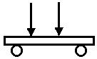
2 - Tube Fixation: The tube
should have a special fixation; a fixation that allows motion of the tube
as it elongates and prevents its rotation about its center line to avoid
buckling. Sometimes the tube is clamped to avoid the latter motion. In
some cases, the tube is fixed between two rollers to allow the tube to
move. An additional advantage to the rollers is that since they roll during
bending, the tube does not experience any friction, opposing to what could
have happened when the rollers are fixed.

1 - Three point bending: Type
of bending in which the bending force is applied only on one point, and
the tube is fixed on two other points. These force produces a maximum moment
at the midpoint between the two supports.
2 - Four point bending: The
bending force is applied on two points, and the tube is fixed on two supports
at two other points.
Three point bending has an advantage over the four point bending is that in the first, the maximum moment happens only on one point, while on the second, it takes place on a range. Therefore, there is a greater probability for defects and imperfections to be present in the volume of material between the loading points in the 4-points bending than in the much smaller volume under the single load in the 3-point test.
 |
 |
|
|
|
The value of maximum stress due to a bending
moment is given as:
![]()
In this case the stress should exceed
the yield stress.
On the other side, the minimum bend radius
of a given sheet or pipe depends on the R/T ratio, which is the ratio between
the bending radius to the thickness (T) of the piece. The relation is given
as:
![]()
Where r is the final radius of the tube
after bending.
Another factor is the Spring back factor
Ks , which is determined as follows:

Where Ri is the initial bend radius and
Rf is the final bend radius.
A spring back factor K=1 means that no
spring back will occur. If K=0, it indicates complete elastic recovery
after the removal of the load.
| Ensley Tools Bending MachineEnsley Tools companyAn exact model for the assigned machine. The force is applied using a hydraulic jack that is mounted vertically on the work piece. The dies contains slots for the tube to be inserted in. In addition, it has two rollers for the tube to slide freely on them. | |
| Manual Hydraulic Bender: Horizontal JackJesan Kovo company | |
| Manual Mechanical Bending Machine:The source of force is the physical power derived from the moving of the handle, which creates a motion and a moment that bends the pipe. This model may have some limitations for the possible limits of bending. | |
| Manual Draw Bender:Draw bending machines let you bend pipe and tube at extremely low cost. The compact design permits a great deal of mobility, as well as flexibility of location. They are light-weight and require less than half square meter of bench space--including the bend arm sweep. The limitation of this machine is tube size limitation; it can work for all cross-sections. | 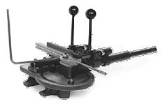 |
The machine that was selected for manufacturing is the first model, based on the Ensley tool machine. A large part of the project was done using Reverse Engineering. First, using the internet and getting manuals for similar machines. Next, a similar model for the machine was studied thoroughly and its measurements was taken. Finally, a new design was implemented to overcome the problems of the large price and other problems of the original design.
The machine is composed of the following main components:
1 - Bender Frame: These are
two identical plates between which the tube is supposed to rest. It should
be strong and rigid so as not to move during the bending process, causing
any of the previously mentioned defects.
2 - Rollers: They represent
two points of the three points bending. They tube should rest on these
rollers. Therefore, they should have additional mobilities (translation
and rotation along its center line) to allow the sliding of the tube over
them, else the tube surface will deform due to friction between it and
the rollers. The slot engraved inside the rollers should fit the cross
section of the largest tube section that machine is supposed to bend.
3 - Die: The die is the point
of force application. It is circular sector with a slot engraved in it
for the tube to rest on. The machine should have a special die set for
each tube section.
4 - Hydraulic Jack: This
is the source of the force. The used on is a 20 ton jack, however it should
be used on a vertical direction. It total stroke is around 26 cm.
5 - Others: Table, fixations
between the bender and the table, fixation between the jack head and the
die.
As the jack moves upwards, the die moves
until it meets the work piece. The three points in contact with piece;
therefore bending starts. The jack gives a small feed of motion (2 mm per
time). This is important because if its minimum feed was high, it could
have caused sudden fracture. The small feed is an advantage because it
gives a chance for very reliable and precision bending.
The implemented design uses the vertical jack setting: Ensley Tools Machine: This offers:
1 - Maximum Stability: By
comparing Ensley tools model which is fixed on a table to the one of Jesan
Kovo, it is clear that the tripod fixation is not as stable as being fixed
to a table. This is because when a force is applied on the jack arm, there
will be a tendency for the whole machine to rotate over one of the tripod
struts. Accordingly, by avoiding the tripod, more stability was achieved.
2 - Less Price: The price
of the horizontal jacks in comparison to vertical jacks is very high (around
2000 L.E. for the horizontal to just 90 L.E. for the vertical jack with
the same capacity20 tons). Therefore, it is more economical to use the
vertical bender.
Steel was chosen for the machine parts for the following reasons:
1 - Low cost
2 - Easy to machine, in comparison
to Aluminum or other materials.
3 - High strength that can
withstand the loads.
4 - Long expected life-durable.
Steel pipes may be made from slabs or billets.
The slabs usually are processed to make welded pipes. Seamless pipes are
normally made from billets. The slabs are reduced to narrow strips called
skelp. The skelp is as wide as the circumference of the pipe to be produced.
A machine draws the skelp through a bell, or bell-like die, or through
contoured rolls. The bell or rolls bend the strip of steel into the rounded
shape of pipe or tubing. The seam is then electrically welded.
In order to make large-diameter
pipe, a steel plate is pressed by machines into the general contours of
pipe. The seam is welded, and the ends are temporarily sealed. Water is
then pumped into the pipe under pressure, and this expands the pipe hydraulically
to the right diameter.
Billets are reduced to bar-like
lengths, which are called tube rounds, before they are made into seamless
tubing or pipe. The tube round is first heated to a uniform temperature
in a continuous oven. Then one end is fed between the piercing rolls of
a mandrel mill. The rolls work and knead the round until an opening develops
through the center. A mandrel, or piercer, is inserted into the hole of
the tube round. The process is continuous. The round moves forward, opening
into the shape of a pipe or tube as it passes over the long mandrel. After
an opening is made through the entire length of the round, the mandrel
is withdrawn. The pipe may be further shaped by elongating in a stretch-reducing
mill; or it may be enlarged by being passed over a sizing mandrel, which
operates in the same way as the piercing mandrel. While a mandrel is inside,
the tubing or pipe may also be worked between rolls, or reelers. The pressure
of the reelers thins the outside wall of the pipe or tubing.
Tubing is sometimes cold-drawn
through a die while a long mandrel is inserted inside the tubing. This
technique enlarges the diameter of the tubing. The pressure of cold-drawing
can also result in tubing that has a greater tensile strength and a smoother,
tougher surface.
Introduction to Machine tools
A machine tool is a power-driven tool that
changes the size, shape, or finish of metal objects. A true machine tool
does at least four things: It holds a workpiece, holds a cutting tool,
moves one or both of these objects, and provides a feeding movement for
the tool or the workpiece.
The cutting tool makes a new part
by shaving metal from an original piece. A machine tool carves a piece
of metal in much the same way that a pocket knife is used to whittle a
toy sailboat from a piece of wood.
An important feature of a modern
machine tool is precision. It can cut metal to an accuracy of millionths
of an inch. This figure is approximately equal to 1/300 of the thickness
of a human hair. Such precision makes it possible to produce two parts
or thousands of parts that are exactly alike.
There are more than 400 kinds of
machine tools at work in industry today. They range from small bench devices
to complicated machines that weigh hundreds of tons. Machine tools perform
thousands of operations primarily on metal objects. They produce tiny screws
and great turbine rotors with precision.
In principle machine tools are simple.
They perform some basic operations on metals. These operations are turning,
planing, milling, drilling, power sawing, grinding, and metalworking.
In our project, several metal working operations were used. We were basically limited by the tools available at the AUC workshop. Some operations would have required more appropriate tools and manufacturing processes.
The basic maunfacturing processes that we practiced during our work on the project are the following.
1- Turning
The lathe is the machine tool used to
perform turning operations. It produces a cutting action by rotating a
workpiece against a fixed tool having a single edge. The line of cut forms
a cylindrical surface. The principle of the lathe has been known and used
for hundreds of years. It probably developed from an early combination
of the potter's wheel and a knife.
A lathe is the most versatile machine tool.
It can machine a workpiece to a round, a concentric, an eccentric, or a
tapered shape. It can cut plain or tapered screw threads inside or outside.
With the proper attachments, a lathe can perform milling or grinding operations.
It does all work with precision.
Principal Parts of the Lathe
The bed is the frame that supports
the tool and the workpiece. The headstock supplies mechanical power. It
contains a cone pulley that provides variable operating speeds. The tailstock
controls the dead center that supports the end of the workpiece. The carriage
moves and controls the tool. A compound rest holds the tool post and the
cutting tool. The cutting tool is made of tempered steel or of steel tipped
with alloys such as the carbides of tungsten, boron, titanium, or tantalum.
In operation the workpiece may have a
hole drilled in each end and be held rigidly between centers. The workpiece
may also be held in chucks. In either case the workpiece rotates, and the
tool is fed into it.
Types of Lathes
The engine lathe is the type most
widely used. It has back gears to provide the low speed and high torque
required to make heavy cuts on a large workpiece. An engine lathe is built
with change gears and a lead screw for cutting threads. It also has powered
feed in both longitudinal and cross directions.
- Turning was one of the processes
that we used extensively during our labwork. The rollers were manufactured
by turning. We used a special tool with an especially designed contour
to work the rollers.
- Turning was also used a
basic cleaning operation. We removed 2mm of the surface of our materials
to remove the oxidation and dirt. Facial turning was also used, as well
as longitudinal turning.
- The die was also manufactured
by turning a large disc. The disc was latet sawed to obtain an arc-shaped
die.
- Large bolts were machined
to the appropriate size by turning. We also threaded them using the lathe,
with great precision and improved surface finish.
- The die fixation problem
was also solved by turning. We manufactured an especially designed part
that enabled us to fix the die over the piston head.
2- Shaping
Planing Operations
Planing metal with a machine
tool is similar to planing wood with a hand plane. The planer produces
a flat surface by its cutting action. A single-edged tool is held in a
toolhead on a rigid cross member called a rail. The workpiece is mounted
on a table that is supported by tracks in a heavy bed. Cutting action takes
place when the workpiece is moved back and forth against the stationary
cutting tool.
A shaper is a machine tool that
is used to plane metal. A shaper's single-edged tool moves back and forth
in a straight line, and the workpiece is fed into the cutting tool. The
standard shaper consists of a base on which is mounted a column that supports
the operating parts. A ram over the column carries the toolhead. It travels
in ramways that control the tool's motion.
Shapers are used for machining
small flat or curved surfaces.
- Shaping was one of the operations
that we used to manufacture our machine.
We used the shaper to improve the dimensional
accuracy and surface finish of the plates borders. The plates were originally
cut using an oxy-acetylene flame. The resulting surface finish was very
bad. A shaping operation was needed to remove excess metal and to increase
the dimensional accuracy of the workpiece.
A milling machine is used to form flat,
curved, or irregular surfaces. The cutting action occurs when a workpiece
is fed against one or more rotating tools called milling cutters, or mills.
This operation is exactly opposite to that of a lathe, which removes metal
by feeding a tool into a rotating workpiece.
The general-purpose milling machine
performs a variety of operations. Column-and-knee, manufacturing, and planer
types are examples.
Special milling machines include the planetary
type for hole and facing operations and double-end machines for milling
the ends of rods and shafts.
Principal Parts of a Milling Machine
The column-and-knee type is a milling
machine that has many industrial uses. It consists of a base that supports
a column. The front of the column is the face. A part known as the knee
projects from the column and moves up and down on the face. It supports
a table that travels horizontally on tracks called ways. An overarm supports
the toolhead. The milling cutter is mounted on an electrically driven spindle
or on a part called an arbor held by the spindle.
In general a milling cutter has a cylindrical
body that rotates on its own axis. It is designed with equally spaced cutting
teeth that engage the workpiece in regular sequence. Plain-milling cutters
have teeth on the perimeter only. They produce flat surfaces parallel to
the cutting axis. An end-milling cutter has teeth on the end as well as
on the perimeter. Face-milling cutters have teeth on one or both sides
as well as on the end of the cutter. An angle-milling cutter is shaped
like the frustum of a cone. It is used to make angular cuts such as grooves
and V notches.
The operation of plain, or surface,
milling consists of machining a flat, horizontal surface with a plain-milling
cutter. If the cut is much wider than the diameter of the cutter, the process
is called slabbing. End milling is used for cutting slots, facing narrow
surfaces, and making accurate holes. Face, or side, milling is the process
of cutting vertical surfaces at right angles to the cutter's axis.
Milling operations are very slow and costy.
However, the surface finish and dimensional accuracy is increased. In our
project, milling was the least used manufacturing operation.
We used the milling machine to improve
the surface finish and dimensional accuracy of a 9cm hole in a 0.9 mm thick
plate. The hole was origoinally drilled with the lathe machine.
Throughout our work on the project, several
hole making oprations were performed. We had to make holes in different
plates in order to implement the designs.
The hole making operations we performed
ranged from 0.8 mm to 1.2 mm thick plates.
The holes ranged from 4mm to 22mm diameter
holes.
The process of making a finished hole
is one that may require several steps. The first operation produced a rough
hole. It was then necessary to enlarge the hole in order to obtain greater
precision. Finally, a special finish, such as a thread, was cut on the
inside of the hole.
Drilling Operations:
The simple cutting of holes in or
through metal is called drilling. It is done by a rotating tool called
a drill that has multiple cutting edges at its point. The power-driven
machine that holds, rotates, and feeds the drill is called a drill press.
There are two standard drill
presses in the AUC workshop. The sensitive type is used for light work.
The bench type is a small machine with a column for mounting on a bench.
It is used on a short workpiece of medium size. The toolhead can be swung
around the support column as well as toward or away from it. These two
motions produce radial action.
To manufacture our machine, a 9cm diameter
hole had to be made in an 0.9mm thick steel plate. For this process, the
usual drilling machine was unappropriate. We had to use the center lathe
with a proper tool to manufacture the hole. However, the surface finish
and dimensional accuracy needed improvement, so the workpiece was taken
to the milling machine (see previous section, "milling")
In many manufacturing operations power
sawing is the best method for cutting metal. It is an economical way in
which to saw bar stock to the approximate size needed for further work.
Contour cutting can be done accurately and quickly by power sawing.
To manufacture our machine, we went through
several sawing processes. Various cylinders and angles bars were cut to
appropriate dimensions for further machining. We also sawed 10mm plates.
We encoutered two different sawing machines
during our work. One was at the AUC workshop and the other one during the
steel buying process (in a Sabteyya workshop).
Circular Saw
The circular saw consists of a large,
power-driven blade with inserted teeth. Its action is similar in many ways
to that of a milling cutter. The circular saw is used mainly to cut bar
stock to a desired length. It runs at slow speeds but has great power.
Reciprocating Saw
A reciprocating, or power hack,
saw cuts stock slowly but cheaply. A cranking device raises and lowers
the blade after each stroke. This tool is provided with an automatic cutoff
that stops the machine when the stock is severed. Several bars can be cut
at one time.
Manual sawing was also used to manufacture
our machine. Small parts that could not fit on the electric sawing machine
had to be sawed manually with a handsaw. Manual sawing helps control the
accuracy of the cutting and intricate cuts can be performed.
We also sheared parts of the angle beams
to manufacture the stand. Triangular sections were cut of the ends of the
angle beams to weld them together.
Grinding was used extensively during our
labwork. The dimensional accuracy and surface finish was improved my griding
the edges of the plates. We used both manual and electric griding. Sharp
edges as well as excess metal were removed by grinding.
-Welding:
Welding, brazing, or soldering processes
join two metallic surfaces by creating bonds between their constituent
atoms. In welding we frequently use a filler material between the surfaces,
and all three apply heat to melt either the local surfaces or the filler.
During the process the surfaces are protected from the oxygen in air, which
tends to combine with the metallic atoms thus decreasing the strength of
the bond, by the use of a chemical flux, which cleans the surfaces, or
by immersion in a protective atmosphere. Welding provides the greatest
junction strength. In a proper weld the joint will be as strong as the
parent material sometimes stronger.
In welding, two metal sections
are normally joined by bringing their surfaces into contact under high
temperature, high pressure, or both, depending on the application. Although
most welds are made between similar metals, different compatible metals
may also be welded.
The principle method we used throughout
our labwork is gas welding, using Oxyacetylene.
Gas welding uses a flame to melt the local
material and the filler. The filler is usually a metal rod that is allowed
to flow between the parts to be joined. The flame also provides a protective
atmosphere that discourages accumulation of oxides. Gas welding is used
primarily for repairs in areas where portable equipment is an advantage.
Arc welding uses the intense
heat of an electrical arc generated when a high current flows between the
base metal and an electrode. Temperatures of up to 3,870 C are applied
to melt the local base and filler materials. Shielded metal-arc welding
uses electrodes made of a coated metal filler wire. The electrical arc
breaks down the coating to provide a protective atmosphere that both stabilizes
the arc and acts as a flux. In gas-tungsten arc welding a non-melting tungsten
electrode holds the arc, and an inert gas, such as nitrogen or argon, provides
the protective atmosphere. Meanwhile a filler wire is fed through the electrode
holder. Since no separate flux is used, the quality of the resulting weld
depends heavily on the cleanliness of the initial surfaces.
We used welding operations to manufacture
our stand. 4 angle bars and a plate were welded to produce the stand, in
addition to 4 other angle bars to form the legs. In this operation, oxy-acetylene
welding was used.
We also used welding to join several plates
to the bender frame. The piston "box" (the three plates that surround the
piston) were fixed on the table by welding.
To fix the spring on the die, we welded
a small bent steel part on the die as well as on the piston box.
During our labwork, we also performed temporary welding processes. The steel frame consists of two plates. In order for the two plates to be identical, we had to machine them together. We performed a temporary welding operation to join them and be able to machine them in a single step.
The oxy-acetylene process was also used to cut steel plates. In this process, the torch provides a higher oxygen to fuel ratio. The oxy-acetylene cutting process was used to cut our steel plates to the desired dimensions. It was also used to cut the arc-shaped part from the disc.
The oxy-acetylene cutting process has a very poor surface finish and dimensional accuracy. The cut part must undergo at least a further machining operation, such as shaping or milling.
1 - The size of the plates
used in the frames is heavy. Though it increases the machine stability,
it should be considered to decrease the plates thickness when implementing
similar model. This may result in decrease in price.
The price of a similar machine that was
purchased by AUC maintenance (Plumbers) was around 2800 L.E. The produced
model cost around 400 L.E., though some costs were spent on needless parts
because of the forced changes in design. In general, it was an economically
feasible machine when talking about a very small production. On mass production
limit, the machine will definitely have less cost.
Another machine, but with only 12 tons
jack capacity, costs 600 L.E.
Colliers Encyclopaedia. Manufacturing Processes. 1997.
Kalpakjian, Serope. Manufacturing Processes
for Engineering Materials. Addision Wesley,
USA. 3rd Ed. 1997.
http://www.pvtnet.cz/www/jesankovo/j05.htm#XOTR29
http://www.ensley-tools.com/8.html
http://www.pro-tools.com/Page11.html
http://www.phi-tulip.com/benders/manbend.html
We would like to express our deep appreciation
to Dr. Hani A. Arafa () for his support for us during the project
implementation in the work shop. He contributed to the design of the machine,
and perhaps for all the 339 class, especially when we consulted him concerning
the springs and some other challenges that we faced during the project.