
A photo of the salt water capacitor I first used to see if my tesla coil would even work. This cap consisted of 6-8 assorted glass bottles in a 10 gallon fish aquarium. The bottles sit on top of a piece of aluminum foil placed in the bottom of the tank. The bottles and tank are then filled with saturated salt water. Add a few pounds of salt (table salt, rock salt, ice-melt salt...anything that is an ionic compound will do) stir, then add some more salt. It may take a few hours, but finally no more salt will dissolve and the excess will sit on the bottom of the tank. (This won't degrade performance) I then rolled aluminum foil into thin strips and placed this through the neck of each bottle to make jumpers from bottle to bottle. A two inch layer of corn oil suppressed any arcs from the top of the water. The inside-the-bottle jumpers are one capacitor terminal, while the aluminum sheet at the bottom of the tank is the other.
This
capacitor was fairly messy, can't travel well, and you will most likely
break a bottle if you have too much power. But it was dirt cheap,
easy to make and rebuild and it worked!
Corn oil...they said you can't use it...
Polyethylene Rolled Capacitor


Well, if you had a better picture of the three gallons of veggie oil above, you would see that the label states "AN IDEAL ALL PURPOSE OIL -- GREAT FOR SALADS, FRYING, AND BAKING". They don't know the half of it! I'd have to say it's excellent for frying, especially those AOL CD's!
Anyway, the other photo displays the components I used to roll the capacitor. To get started, I made the small white box (6" wide x 12" tall x 18" long) and sealed the three sides and bottom with RTV silicone. The fourth side has an oil seal and is removable. After I cleaned and prepped the sheets, I screwed a sandwich of poly-Al-poly to the PVC pipe, then set the pipe in the box with the sheets exiting the top, and pressed on the removable end and sealed it to the box. It took the full three gallons of oil to bring the oil up to a decent level in the box. I began winding, on the first trip around, I inserted a 1" x 16" scrap of plastic over the screw heads, and on the next half turn, I inserted the second Al sheet. In this manner, the cap is wound UNDER the oil which eliminates most if not all of the trapped air in the sheets without the need for a vacuum pump.
I figure I used a total of about 1-1/2 gallons of oil for the cap, poured 1 gallon back into the container for later use, and spilled about 1/2 gallon on the garage floor when I missed the bottle neck!
This
cap measured .0185 uF which is still a little low for my coil.
12-22-98
- A couple of weekends ago, I had time to add on to my .0185 uF cap.
I used the third 16" wide strip of LDPE cut from my original 4'x8' sheet.
I cut this third sheet into two 4' lengths. These sheets, and two
more aluminum flashing plates made a .0078 uF capacitor. Technically,
this .0078 uF cap is running in parallel with my .0185 uF cap for a total
of .0263 uF. Actually, they are both wound in a coaxial fashion around
the same center, and sit in the same PVC pipe...so outward appearance is
that of a single cap. Also, I made another container for the cap.
This one is made from the same material, with the only exception being
to use a pipe that is 24" long instead of 20". The reason works like
this: The first cap container was 20" tall...inside was a 1" tall
"star" on the bottom for oil circulation, a 16" tall coil of LDPE, and
2" of oil to cover the cap. Now 1+16+2 is 19 inches, so every time
I moved the container, oil would spill out the top or at least seep around
the lid. I know, I can hear it now..."Why don't you seal the lid
on, dummy!" Well, if this thing does blow, I'd much rather see a
small gush of oil out the top than be standing beside a 6"x20" pipe bomb.
1-14-98
- I'm back from the holidays. The coil took a turn for the worst
on Christmas Eve. I sat it up for an outside run. (My first
ever) The temp hovered around 10 F degrees with just the slightest
breeze (maybe 1-2 MPH). Dusk fell and family and friends gathered
around. I twisted the knob and the coil crackled to life. It
was the first time I had observed arcs form on the windward side and dance
around to the opposite side of the coil. I ran the coil for several
minutes and shut down to reposition some ground rods, adjust the spark
gap, and explain some TC theory to the group. After a couple of minutes,
I fired the coil back up. It ran for a few more minutes when all
of the sudden a couple of arcs flashed from the toroid to the capacitor
terminals. I suppose it's worth noting at this point that these terminals
were a few inches below and about 5 inches farther out than the strike
rail. To make a long story short, I tried to grab the variac to shut
down the power. But about the same time my hand hit the controller,
the cap died. I guess the direct strike voltage was just too much,
and of course once it's blown, it's blown.
1-31-98 - I had time to autopsy the cap today, it turns out the trouble centered around a 1/8" diameter hole in the LDPE located about 1/4" down from the edge of the Al plate. Close examination of the area didn't reveal much in the way of a cause. I can only speculate that a small scratch or other imperfection in the LDPE made this the weakest spot. The LDPE is really hard to get in "pristine" condition as it comes in a 4' x 8' sheet that apparently gets slid on and off shelfs, across the floor, down the wall, etc. before you ever get your hands on it. This treatment results in numerous tiny scratches and gouges. Anyway I cut out the bad sections and rebuilt the cap. It's down to about .024 uF now, but this is actually a closer match to my NST and I can make up the difference with the modified primary.

New Technology...My Multiple Mini
Capacitor (MMC)
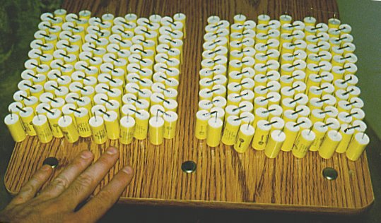
Well, there it is. The cap consists of 12 strings in parallel with 22 series caps in each string. The specs for an individual capacitor are as follows:
Manufacturer:
General Electric
Mfr. Number:
42L2152
Capacitance:
0.15 uF +/- 5%
Rated Voltage:
1200 VDC, 500 VAC

This is a detail view of the capacitors attached in a string with 10meg bleeder resistors. I started with the #1 cap at the lower left hand side of the pic. The lead on the back side (red line) bends up and to the right, while the lead from cap #2 bends down and to the left. The two are soldered side by side. Then on the visible side, the steps are repeated for cap #2 to #3 connection. The string is repeated until the desired number of caps are attached. Bleeder resistors are then attached between the paralleled leads on both sides. This method has several advantages: elimination of excess wire (hence induction) between caps, the leads are doubled for lower resistance, the caps are tightly packed, no PC board required. On the down side, each of the cap leads has to be fairly precisely and equally trimmed (I made a small jig), same goes for resistors. It's sometimes hard to hold two caps, solder, soldering iron and get the leads to line up...but I had over 300 caps to practice on!
Overall, putting each of the strings above in series, the cap would be .082uF and about 26,000 VAC using peak DC voltage equals peak AC voltage. I think that by the time I consider all of the cutting and soldering time for not only the caps, but also on the bleeder resistors (not shown), this cap actually took more time than my corn oil cap. BUT here is the catch:

This is a comparison between my homemade corn oil cap which has served very well in the past year and a half of service. But consider the oil cap (left) is about .024 uF and is on the ragged edge with my 12KV transformer. The MMC module in the center is .034 uF and easily handled the 12KV, even as I bumped the spark gap open a little. The beer can is there for scale. I'm only using a portion of the MMC because I'm still running with my 12 KV NST. I plan to get a 9KV, 450 mA unit running by summer. The new NST will use all .082 uF from 12 strings in parallel.

Here is a photo showing the initial mock-up of my 9/450 NST with the MMC. The full MMC consists of 12 parallel strings of 22 capacitors and measures 84nF at 22,000 volts (assuming peak AC = peak DC rating). This is monster capacitance in a small package...and relatively cheap. In quantity each cap was less than 70 cents and the only other thing that went into fabrication was solder and some lead wires. So far the output results have been stunning. This cap is actually way voltage over rated for this NST (10,500 V @ 140 volts on the variac) versus 22,000 for the cap. I wanted to err on the side of caution, though. I really need about 100nF to best match the NST.

Finally had a chance to do a bit
of work to my MMC. This incarnation has been wired with 16 strings
in parallel (8 visible, 8 on the opposite side). Each string has
18 caps in series. Total capacitance is 133 nF. It rests on
a solid oak base and a lexan box. The sides and top of the box are
painted with black wrinkle paint, while the sides remain clear.