
Orignal power supply unit (PSU)
Specifications
(Components from Right to Left)
| 1-
12,000VAC / 120mA Neon Sign Transformer (1440 Watts @ 120 VAC input)
Driven through a 0 - 140 VAC 20 amp Variac (Not Shown) |
| 2- 1/2" X 8" Ferrite Rod RF Choke coils |
| 1- Safety Gap |
| 2- Salt Water Bypass Caps. 300 pF each |
| 1- Richard Quick Style Spark Gap 9 Elements (8 gaps) 0.030" per gap |
Notes:
I initially bought the transformer as a 12KVAC / 60mA unit from a local neon sign shop in working (but dusty) condition for $20. I began the de-potting process using a gas BBQ grill to slowly raise the temperature enough to melt the tar without melting the transformer windings. After I had melted as much tar away as possible, I disassembled the unit and placed it in solvent (diesel fuel) for two or three days and finally was able to remove about 97% of the tar. (Just enough tar still remains so that you generally can't touch the transformer without getting a small black smear on something.) Once the transformer was free from the tar, I took the opportunity to increase the output by removing some of the current limiting magnetic shunts. I read somewhere that this was to be accomplished by "tapping two or three of them out" Apparently, "them" refers to the individual laminations in the shunts as opposed to an entire pack of shunts. Anyway, I initially removed 3 of the 4 packs (about 45 out of 60 laminations).
To
measure the output current, I connected my digital multimeter (DMM) to
the two HV leads of the transformer. Make sure the leads are insulated
from each other and from ground and make sure the DMM is insulated as well.
(I just left plenty of air space between the leads, and let the transformer
and meter set on separate sheets of plastic.) Then plug in the transformer
and observe the meter readout from a safe distance. (NEVER attempt to touch
the DMM or leads with the power on!) The DMM survived because in
this configuration, there is no voltage across the meter, only current.
I measured the current at over 370 mA--I don't think this is entirely right,
but I was too scared to switch down to the 400mA scale on my multimeter
to find out. I put as many laminations as I could find back in the
core and the current fell to 120mA (on the 400mA scale) which seems to
be about right. Also...yes, I know, nothing is wired together on
the power board yet. I thought this might make for a less cluttered
view of the components.
10-15-98
Eliminated
SW bypass caps. I think the capacitance was a little large for a
bypass cap. Apparently no change on coil operation with removal.
12-20-98
Re-gapped
the RQ spark gaps, since I never run more than about .150" I changed the
configuration to 9 elements (8 gaps) spaced .020" each. This should
make the gap slightly easier to quench. A total change to a different
design is planned in the near future.
New
(to me) 9,000 Volt Transformer
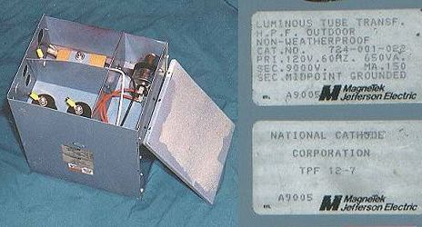

The left is a shot of one of the
9,000 volt 150 mA NST's complete with metal box, HV terminals, PFC capacitor
and a dead man kill switch. The center is a scan of the nameplate,
and on the right is a comparison between the block of tar that lives in
the metal box and a heavy duty truck battery. The NST actually out-weighs
the battery by a considerable amount. I'm hoping that once
all of the tar comes off, I can punch out some of the shunts and get 450
mA with some type of respectable life time.


This is what lives under the 35 pounds of tar. I find that freezing the block of tar and chipping away everything that doesn't look like a NST works well to remove the bulk of the tar. This was followed by heating to 200 degrees F to pull the core apart and separate all the components. I try to keep the temperature to a minimum because it is easier to work with the tar when it is just slightly "gooey". You can still scrape it off like putty. If it gets too hot, the tar will turn into a runny, sticky mess that is very hard to handle. Heat it up, grab some leather gloves you wouldn't mind to throw away and go to town.
Once the components are separated and as much tar has been removed as possible, I go in to the solvent soak for final cleaning. Diesel fuel works well as does kerosene or mineral spirits. Ideally, a mechanics parts washer (I have access to one with Safety-Kleen Premium-150 solvent) works excellent. I tend to stay away from solvents like gasoline and "hotter" solvents like toluene and xylene. One static spark and any of these may go "POOF!" Also, remember the coils are built with varnished magnet wire...you'd prefer not to remove the varnish as well.
When
the solvent has done it's job, usually overnight, I rinse with clean solvent
and go into a 200 degree oven for several hours to bake out the remainder
of the solvent. Do this outside or you will really fume up the house!
The clean dry coils can now be taped (mostly for appearance). I then
wrap with clear mylar for flash-over protection. Re-install on the
core and add some or all of the shunts depending on how much you intend
to increase the amperage output.

8-16-2000
Finally had a few minutes today to drag out another DVM and measure the output of my new NST. My Radioshack meter has a range of 0-400mA and 0-10A. I knew the NST would peg the 400mA scale but the 0-10A scale indicated about 1.25 A...clearly in error. My Fluke meter has a scale of 0-2000 mA AC and reads about what I had anticipated (only slightly higher!) at 490 mA. Also, this is the dangerous way to measure the amps...note the wide air space between the leads and the 1/2 inch thick lexan protecting the meter from "ground". A much better way to measure involves use of a shunt and an AC volt meter.
The 490mA output brings up two problems:
1) with an estimated 5100 watts into the coil, there should be MUCH longer arcs. As Ross said, "There are more arcs in there somewhere!" I know the cap is mis-matched at 82nF while the calculated resonant cap is at 124nF. Simple enough to rewire.
2) The toroid is much too small now. I get arcs from the moment the spark gap begins to fire. The dings and dents from use sure don't help either. I am considering either dual 12 x 40-something toroids or one covered with expandable copper mesh.
I'll have to see where this leads.
The New Plan - Bwah Ha Ha Ha!

I am currently working on a vacuum chamber to impregnate the NST coils with varnish used for coating electric motor coils. This varnish has a dielectric strength of 3500 volts per mil minimum. Once I get some coils coated, I will try running two of the above NST's in SERIES. This should provide up to 21,000 volts at 450mA. (Each NST can be driven through a 0-140 VAC variac for up to 10,500 volts from each.
For all practical purposes, the voltage will be limited to about 15,000 volts (75% output). This will better use my MMC because it is rated to 22,000 volts.