'79-'85 MAZDA RX-7
FORD 5.0 V-8 Conversion Installation Tips & Suggestions
for a successful California Smog Legal Conversion
from Brad Bergholdt

Brad Bergholdt's California smog legal Ford 5.0/AOD powered '83 RX-7
'79-'85 MAZDA RX-7
FORD 5.0 V-8 Conversion Installation Tips & Suggestions
for a successful California Smog Legal Conversion
from Brad Bergholdt
Brad Bergholdt's California smog legal Ford 5.0/AOD powered '83 RX-7
The engine had recently expired in my '83 RX-7, and being rather attached to the car, I didn't want to throw it away (seems to be what's done in this case as rebuilding or replacing the rotary engine is quite expensive). Just prior to the engine problem, I came across Granny's web site, and was surprised to find that RX-7 engine swaps were not only possible, but apparently fairly simple to do. I'm not sure what happened next- It may be that I willed that engine into apex seal failure.
The result, after five or six Fridays work (there's always a few more things to do), and a tad over $1000, is a reliable, incredibly fast car that is fun to drive, and turns heads wherever I go, due to it's deep V-8 growl. I should add the car is California emissions legal, and delivers better fuel economy than it did when equipped with the rotary engine.
Here's how the engine swap went:
As luck would have it, I came across a donor vehicle soon after the Mazda engine bit the dust- a 1989 Lincoln MK-7, with a low mileage 5.0L EFI engine and AOD (four speed overdrive) transmission. This engine has the Fox body engine oil pan and factory exhaust headers, both of which worked out perfectly in the RX-7 chassis. Having access to the complete car was also a blessing, as I was able to remove quite a few accessory items and every bit of wiring and emissions hardware needed.
I installed the Granny's engine mount kit and Napa engine and transmission mounts, and found that fitting/installing the engine/transmission into the chassis was a very tight fit. After mucking around with it for a few hours, I came up with the following "modifications" that would be much easier to do prior to dropping in the engine/transmission:
Relieve (push/beat back) the firewall in the following spots, 3/4 to 1 inch deep, about 2" in diameter:
11" down, 1/2" inboard of windshield washer hose
4" down, 1" inboard of speedometer cable. About even with the frame "rails", right at the curving corner
Next, saw off the driver's side transmission cross member mount (a bulge that protrudes from the RX-7's underbody). This is easy to do, using a sawzall or abrasive disk tool. You may also need to saw off a small tab that protrudes from the AOD transmission case (on the upper right side)- wait until it's in the chassis to see exactly where.
The EFI engine fits into the RX-7 engine bay by the slightest margin on the top bottom and rear. (there's tons of room on the sides and front). Whoever it was at Granny's that designed the mounts did their homework, as the engine pan clears the cross member by around .025" and the EFI plenum clears the hood by about the same margin. Pushing the firewall back allows about 3/8" clearance between the air injection tubes (attached to the rear of the cylinder heads), the exhaust manifold collectors, and the firewall.
The fuel system:
I found that a Ford external (not in-tank) EFI fuel pump works great, mounted just behind the original Mazda fuel pump location. These pumps are used on trucks and several different passenger cars. As long as you prime the pump after installation (blow 2-3PSI compressed air into the fuel tank filler, sealed with a rag) and never run out of gas, the pump does just fine without the low pressure in-tank "pusher" pump used in conjunction with it on the Ford vehicles. I next found the RX-7's metric fuel lines (pressure and return) were easy to couple to domestic 5/16' and 1/4" steel lines (you'll need to cut and double flare the lines near the power brake booster) and drill out the 5/16 brass coupling nut very slightly. I then extended the lines across the firewall (along the top edge) to the passenger side, the fuel filter, and down to the right front corner of the engine. I then bubble flared (the first step of the double flare process) the steel lines, and ran 900PSI EFI rubber hose to the Ford engine's barbed steel fittings (eliminating the original nylon hoses and proprietary fittings). Even though the Mazda had existing fuel pump wiring, I decided to run new (larger) wires, using the Ford fuel pump relay and crash switch (more on this later).
Wiring the engine:
This part is really fairly easy. In addition to the Ford's starting, ignition, and charging wires (seven of them), there are only eighteen wires that need to be spliced to get the EFI system, backup lights, neutral safety switch and gauges operational. First, make sure you have the complete EFI harness, with computer, from the donor vehicle. You'll want to cut off the donor vehicle's chassis wiring harnesses about six inches (car side of connector) from each of the engine connectors mentioned below. This greatly simplifies the hookup, as you'll be making your connections at the five easy to get-to engine connectors listed:
Ford C-153 (black) and C-163 (gray), eight pins apiece (lower left front of the engine).
Ford C-300 (black) and C304 (Gray), eight pins apiece (lower right front of the engine).
Ford C-730 (gray), 3 pins, located near the computer.
These connector numbers and locations may differ slightly if a Mustang or other EFI engine was used, but the wire colors should remain the same.
I chose to mount the ignition coil and starter relay on the left side of the engine compartment, as the battery and existing Mazda wiring were already there. In the steps below, 16 gauge wire is adequate for all connections, except those noted.
1. The Ford starter relay needs a cranking + signal to its red/blue wire, so connect this to the black/pink wire ("neutral safety "out") of Ford connector C-163 (gray 8-pin connector, left front of engine). You'll also need to connect this circuit to the TFI ignition module (red/light blue wire exiting C-300, black 8-pin connector, on the right side of the engine). You'll need to run this and a few other new wires in a piece of convoluted tubing, across the top/front of the engine.
Next, connect a wire between the RX-7's thick black/yellow cranking signal wire (in an unhooked Mazda connector, just in front of/below the brake booster) to the white/pink wire of Ford connector C-163 ("Neutral safety "in"), and across the engine to the white/pink wire ("computer cranking in") exiting C-304 (gray 8-pin connector, right front of engine).
2. The Ford ignition coil needs a key-on + signal to the positive side of the coil (red/light green wire). You'll need to connect this to one of the Mazda's thick black and white wires formerly connected to the ignition coils. The EEC power relay and TFI module also need this signal, so connect a 12 gauge wire across the engine to the red/light green wire located in C-300 (black 8-pin connector, on the right side of the engine. The remaining wires exiting C-300 are not needed, so it's OK to cut them back, and tape them up.
3. The Ford ignition coil needs to receive a -- signal (dark green/yellow wire) from the ignition module, mounted on the engine. Connect a wire from the coil - to the dark green/yellow wire exiting C-304 (gray 8-pin connector, right front of engine). This circuit should also be connected to the Mazda's tachometer, via the yellow/green wire found in the bundle formerly going to the Mazda distributor and coils.
While you're working with C-304, this is a good time to hook up the three black/light green engine ground wires (exiting C-304) to a clean and tight engine ground stud.
To finish things up at C-304, you'll want to run a 12 gauge wire from the connector's black/orange wire (B+ to the computer) and yellow wire (B+ to the fuel pump circuit) across the engine, through a 20A fuse holder (one for each wire) and to battery +, which can be conveniently found at the starter relay + cable connection. The remaining wire (light blue/pink) is not needed.
4. We've got one last EFI system wire to connect, a black/light green wire (O2 sensor heater ground) exiting C-153 (black 8-pin connector, left front of engine). You'll simply need to take this wire to a solid engine ground. C-153 also contains the Ford oil pressure and water temperature sender wires (among a few others that are unneeded), but it's probably easier to run new wires to the Mazda senders installed on the engine (more on this later).
5. If you want to hear the engine run, it will do so now, if you hook up (temporarily) the Mazda's original fuel pump + (blue/green) and ground wires to the Ford fuel pump. It's a good idea to convert to the Ford fuel pump drive circuit (for safety and durability), and run a larger (12 gauge) wire to the pump before driving the car any distance. Before doing this, you'll want to punch through the firewall, and bring the computer inside the car. Here's how the fuel pump is hooked up:
At C-730 (the three wire connector near the computer), you'll find three wires: red, yellow, and tan/light green. The red wire supplies switched + to the fuel pump relay (saved from the donor vehicle), The yellow wire supplies battery + to the fuel pump relay. The tan/light green wire should flow through the inertia switch (crash switch), and to the fuel pump relay. The remaining wire that exits the fuel pump relay (pink/black), should be extended with 12 gauge wire to the fuel pump.
6. Now the gauges. You'll want to connect the Mazda's brown/yellow (oil sender) and yellow/white (temperature sender) to the units installed on the Ford engine. These are found within a long/wide (unplugged) Mazda connector just behind the left shock tower. The Mazda's alternator warning light circuit (yellow/light blue, catch it at the choke-check relay mentioned below) needs to be connected to the Ford alternator wiring harness's light green/red wire, near the voltage regulator. For whatever reason, Mazda tied in this circuit with several other warning indicators, so you'll want to disconnect the choke-check relay (two connectors, one with two wires, the other has four), located behind the left shock tower), and the coolant level "sensor unit" (five wires, located just under the instrument panel, left side). I'm still trying to figure out why they did this.
6. The back-up lights. The Mazda's red/white wire (found in an unhooked connector behind that previously went to the transmission) should be connected to the Ford's black/pink wire, found in C-163 (8-pin gray connector, left front side of the engine). The pink/orange wire also exiting C-163 should be routed, through a fuse, to ignition +.
7. Now we're on the home stretch- the alternator output wire and voltage regulator wires. Ford originally ran a pair of black/orange wires from the alternator, through C-262 (a black connector near the alternator), through a fuse link, and to the battery. This was a lousy idea, as the connector tended to melt. I replaced the two wires with a single 8 gauge wire, and ran it straight to the Mazda's fuse link "block" connection, (formerly a white red wire) located just in front of the left shock tower. I then upgraded the "main" fuse link to a 3mm (12 gauge) loop of wire, as the Ford alternator has the ability to smoke the original Mazda link during heavy charging operation.
The remaining alternator/voltage regulator wires are easily connected from C-262, color by color, to the right-side fender-mounted voltage regulator (don't forget to hook up the alternator warning light wire from step 6 at this time).
How to do a California legal EFI engine swap:
The state of California allows you to swap a wide assortment of engines into your car or truck, as long as the engine is the same year or newer than the chassis, and all of it's emission controls are intact. Problem areas could be a heavy duty vs. light duty truck engine swap, or a CA vs. federal engine swap. Also, I don't believe it's permissible to downgrade from fuel injection to a carburetor, or from a feedback fuel system back to a mechanical one. To play it safe, you'll want to pick up and read the state's engine swap pamphlet (available from the Bureau of Auto Repair), and ask a question or two of the smog referee before getting too far along. Most CA Consumer Assistance Centers (smog referees) are located in a community college, and you should be able to stop by, without an appointment, for some quick advice.
In my case, I swapped a CA 1989 Lincoln MK-7 V-8 engine (same as a Mustang 5.0 HO) into a CA 1983 RX-7. Early Mustang 5.0 engines and all MK-7 5.0 engines are of the speed density type (a MAP sensor is used to calculate airflow), while later ones have a MAF (mass airflow) sensor. The MAF system is more compatible with engine modifications, and can be retrofitted to a speed density engine, if desired. The HO engine found in the Lincoln MK-7 and Mustang produces approximately 70 more horsepower than the stock 5.0 EFI engine, and has factory tubular steel exhaust headers, which fit the RX-7 chassis like they were made for it.
The Lincoln engine was equipped with fuel injection, electronic ignition, and the following emission controls: PCV, air injection, EVAP, EGR, and all related components, wires, and vacuum hoses. The RX-7 came equipped with a carburetor, and a considerable inventory of emissions devices, but no feedback controls. The "chassis" systems of the RX-7 that needed to be retained were the catalytic converter (or a suitable replacement) and the EVAP (charcoal canister and plumbing) system.
This part of the engine swap isn't as bad as it sounds, as most of the needed fuel system and emission controls are integrated into the engine package, with the exception of a few solenoids and relays, which mount to the body, and the catalytic converter. There are five convenient wiring harness connectors exiting the engine harness, each of which was connected to the appropriate RX-7 circuits.
Having a complete donor vehicle is by far the best way to go, as you'll have all the parts and wiring needed, plus the vacuum hose routing sticker. Don't forget to write down the VIN number of the donor vehicle, for the referee's use, and for yourself- for future engine adjustments/repairs. Also, I utilized the Lincoln's AOD four speed automatic transmission (the overdrive is nice, considering the RX-7's 3.90 rear gears), never separating it from the engine during removal or installation into the RX-7
Having kept the computer engine/transmission harness fully connected, and all solenoids and relays still attached to it, I laid this out in the Mazda engine compartment, looking for the best routing and mounting locations. I decided to mount the TAB (thermactor air bypass) and TAD (thermactor air divert) solenoids on the RX-7 firewall, along with the EEC (main system) power relay, MAP sensor, and EGR solenoid. These were lined up on the right side of the firewall, behind the windshield washer bottle. It was necessary to splice/lengthen the MAP, TAB and TAD solenoid wires about a foot, so the main wiring harness could be routed below the parts, and through the firewall (the computer needs to be mounted inside the cabin for protection). The only emission device that wasn't "self contained" on or very near the Lincoln engine was the EVAP solenoid. All that was needed here was to route a hose (the larger of the two) from the original RX-7 EVAP charcoal canister (right side of the engine compartment) to the solenoid. Now, the Lincoln computer purges the Mazda charcoal canister, as if it were its own.
That's about it for the under-hood emissions stuff! My donor vehicle didn't have a check engine (MIL) light. If it had, I would have needed to add a MIL light to the Mazda dash, and connect a couple of additional wires.
Now the catalytic converter. The referee's application manual states that the 1983 RX-7 needs an "oxidizing catalyst" (doesn't say how many). I didn't want to run the original RX-7 exhaust, as it was a tangle of heavy pipes, two catalytic converters, and a mass of rattling heat shields. Instead, I fabricated my own two-into-one Y-pipe, welded to the Lincoln's 02 sensor equipped header collectors. (J.C Whitney pre-bent 90 degree and 45 degree aluminized pipes worked great) and sent the two 2-1/4" pipes into a 3" Flowmaster collector), then fed it to a Catco (aftermarket) 3" in, 3" out TWC (three way) catalytic converter. I opted for the TWC cat, as the Lincoln engine had down-stream air injection (that needed to be utilized), and it was difficult to find a 3" oxidizing cat with the needed air inlet tube. The smog referee was OK with substituting the TWC cat for the oxidizing type, as it is superior in emissions performance, and matched the type the Lincoln originally came with. Further downstream is a Flowmaster 3" in, dual 2-1/2 out 50 series muffler. The exhaust tips look like the original RX-7's, but it definitely doesn't sound like a rotary (more like a big-block Chevy). I should add that I retained some of the Mazda floor heat shields, and fabricated additional ones in the needed locations to help keep things cool.
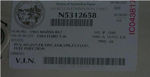
After completing the engine swap, I made an appointment with the state (smog) referee. He was a friendly gent, and was pleased that I had the Lincoln VIN number, and the smog devices neatly organized. After a visual inspection, he ran the car on the smog machine (very clean numbers), and performed a functional test of the EGR system, ignition timing, and fuel tank cap (they all passed). I then received the coveted door jamb sticker, and after paying $38.25 ($30-inspection, $8.25-smog certificate), I was on my way. Next time I need a smog inspection, I can take it anywhere, thanks to the attached BAR label.