...LS1 Engine Cradle Installation...
...9/16" wrench
...5/8" wrench
...3/4" wrench
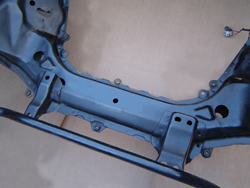
...The Aluminum Engine Spuds go in from the top through the 2 through holes (appx. 1.180" dia., and about 18" apart) in the front crossmember behind the steering rack. They function to spread the stress evenly between the two halves of the hollow front crossmember and prevent collapsing.
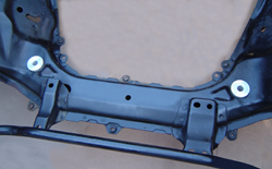
On these applications, the steering rack mounting bolts will need to be temporarily removed to allow installation of the aluminum spud.
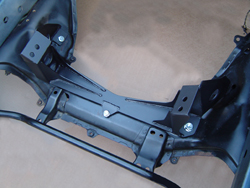
...The two 1/4" thick spud washers install from the bottom with the 1/2" x 3-1/4" bolts. The bolts go through the spud washers, spuds, and through the lower legs of the engine cradle. The lockwashers and nuts are assembled loosely. Install the 7/16" dia. bolt through the center hole in the engine cradle and the existing center hole in the crossmember and loosely assemble with the lockwasher and nut. Loosely assemble the 1/2" x 1" bolts and nuts through the rear strut tabs and the stock engine mount holes in the chassis.
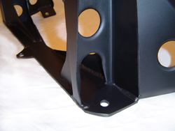
NOTE: on models w/ Power steering, the steel lines from the control valve to the slave cyl. must be routed through the lower hole in the left upright of the cradle.
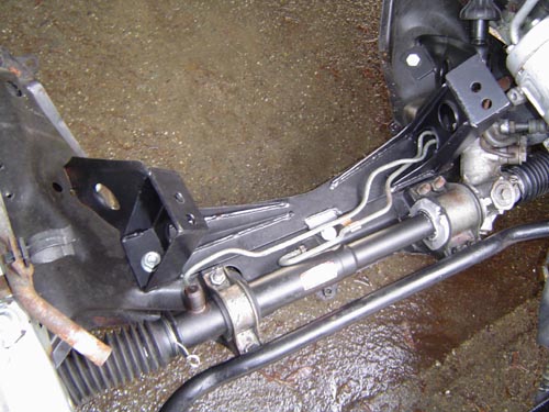
TROUBLESHOOTING NOTE: Ocassionally, someone will call after starting up their car, touching the steering wheel, and experiencing a violent shaking of the wheel, which continues until the engine is shut off. The cause is the hardlines/fittings (the steel lines that run out to the piston portion in the center of the rack) were re-connected to the wrong ports when the lines were re-installed (after installation of the engine cradle). It's easy to mix these connections up, so be sure to mark the tubes and re-install them into the same ports they come out of.
...Check to be sure everything fits properly, then finish torque the cradle to chassis bolts.
7/16" bolts.....................40 ft/lbs
1/2" bolts.......................50 ft/lbs
(an exception is the front center bolt in the engine cradle. 15 ft/lbs will prevent crushing)
...Loosely bolt the rubber engine side mounts into place on the side of the engine.
...Remove the sway bar attaching brackets from the chassis and let the bar hang free.
Pre-Installation Cleaning / Detailing...
...This is probably your last chance to easily detail those places remote and
inaccessible, so take a quick look around before it's too late.
Rigging Engine/Trans For Installation...
...For installation, the engine/trans should be rigged so that they naturally hang
level, or slightly tail down.
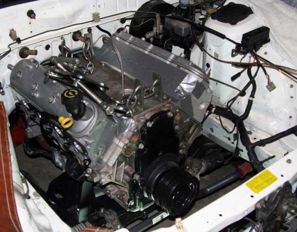
Dropping the Engine / Transmission into Position...
...Carefully lower the engine and transmission assembly into place. Line up and install the two 7/16x1" socket head bolts and lockwashers
through the upper legs of the engine cradle and into the rubber side mounts loosely.
Minor flexing mat be required, but the fit should be tight (use the front set of holes).
...After the engine/trans are in their approximate position, support the transmission,
with a floor jack or jackstand, with the output shaft centerline temporarily lowered to about 6-1/4" below the top
of the transmission tunnel.
...Remove the engine hoist and chains.
...Torque the (2) rubber mount/cradle socket head bolts to 25 ft/lbs
...Transmission Crossmember Installation...
...14mm wrench
...14mm socket, rachet, and 6" extension
...3/8" allen socket
...9/16" wrench
...9/16" socket and torque wrench
4L60E/T-56 Truss Style Transmission Crossmember Installation...
...Remove the shield that covers the fuel lines on the left side/bottom of the
floor pan, where they pass by the rear of the transmission.
...Install and loosely bolt the rubber transmission mount pad onto the transmission.
...Loosely bolt the crossmember onto the rubber trans mount pad.
...Tighten all the installed trans mount and crossmember bolts. Properly positioned, the
crossmember spans the distance between the frame rails, leaving enough room for the fuel and
brake lines. Re-locating the fuel and brake lines is not required.
...Using a 3/8" drill bit, drill holes in the floor pan thru the (6) holes in the ends of
the trans crossmember (2 holes on each end).
...Install the supplied bolt plates from the top side of the floor pan, thru the new
drilled holes.
...From the bottom side of the floor pan, bolt the trans crossmember onto the bolt
plate studs, using the washers and nuts supplied. Tighten the bolts.
...Remove the floor jack (or jack stand) from under the transmission. The
engine/trans should now be resting on it's own mounts, and supported by the chassis.
...Tighten all the bolts attaching the engine cradle to the chassis, torquing the (4) 1/2" dia bolts to 45ft/lbs. Tighten the remaining 3/8" dia center bolt in the base of the cradle just enough to snug the cradle tab to the chassis. The supplied self locking nut will prevent it's loosening.
...Install sway bar spacers if required and re-attach sway bar.
...Checking Drivetrain Alignment / Clearances...
...The properly installed Chevy engine is centered in the car. The RX-7's rear
differential's pinion flange is offset 3/4" to the right of center. This is normal. The
engine/trans and the rear diff's pinion centerline should be parallel, but NOT concentric.
If the centerlines were concentric (exactly lined up with each other), the u-joints would
fail prematurely as they need at least slight internal movement to lube properly.
...The assembled driveline & slip yoke can be installed. The (4) pinion flange bolts should be
torqued to 27 ft/lb (Turbo II 43ft/lb). At least 3/8" of clearance should exist between all parts of the
driveline / transmission tunnel.
Be sure to double check clearances at the...
....steering rack / oil pan
....intake fitting / firewall
....harmonic balancer/ sway bar
....hood / throttle body
...Connecting The Back-up Lite Switch...
...to operate the RX-7's back-up lites, Mazda used a transmission mounted SPST switch to complete the circuit.
When the RX-7's engine harness is removed with the rotary engine, part of this circuit is removed as well.
To restore this circuit, a harness extension will need to be added at connector X-04,
a rectangular 6 pole connector (2 rows of 3) located under the hood on the driver's side of the brake master cylinder.
2 of the wires in this connector are for the back-up lite switch. These wires wires are...
...black wire w/ yellow stripe- comes from 7.5a fuse in underdash fusebox.
...red wire w/ green stripe- goes to back-up lites.
Connecting these two wires together w/ a jumper wire will turn on the RX-7's back-up lites when the ignition switch is in the "ignition" and "start" positions.
Routing and connecting these two wires to your new transmission's back-up lite switch will enable the RX-7 back-up lites when "reverse" position of the shifter is selected.
2....Considerations & Requirements....
4....Engine / Transmission Installation....
5....Exhaust / Throttle Cable / Accessory Drive / Pulleys....
6....Cooling / Fuel Systems....
7....RX-7 Wiring Harness Connector ID and Circuit Locations....
8....Electrical System Modifications By Circuit....