V-8 Subframe Installation...
Install the new subframe, re-using the origional bolts. Be sure to torque all (6) bolts &
nuts to origional specifications.
Installing The Steering Rack...temporarily place the rack in position, while carefully aligning & inserting the
steering column's intermediate shaft into the rack's input shaft/u-joint.
...When the intermediate shaft is in place, install the rack onto the new subframe,
using the origional bolts (14mm socket w/6"extension), torquing them to origional
specifications.
Pre-Installation Cleaning / Detailing...
...This is probably your last chance to easily detail those places remote and
inaccessible, so take a quick look around before it's too late.
Preventitive Maintenance...
...If there is any PM to be done on your new engine, now is the time to do it.
Replace any leaking seals or gaskets. If you want to install a new timing chain, oil pump,
etc, it will never be easier than now.
 Installing RX-7 Water Temp Sending Unit into the LS1...
...temp sender adapter bushing
...RX-7 coolant temp sending unit (NAPA PN# TS-6047)
...anti-seize
...teflon tape
...FYI info- LS1 head coolant plug thread is 12mm x 1.5 pitch
................RX-7 temp sending unit listed above has 8mm x .75 pitch
...On the passeger side LS1 head, remove and discard the existing bolt located just to the rear of the rear exhaust port.
...Using our LS1 Temp Sender Adapter Bushing, install the salvaged sending unit for RX-7's water temp gauge into the hole. Be sure to use anti-sieze and a gasket in the head's threaded hole, and teflon tape on the sending unit's threads.
...tighten carefully to avoid stripping the sending unit's threads.
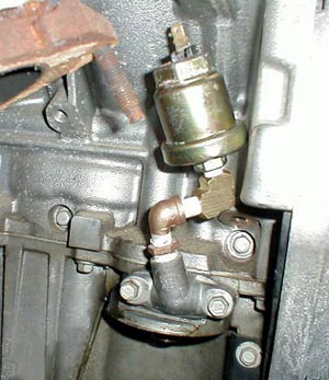
 NOTE:...Some RX-7 sending units have a thread that is very close to 1/8" BPT, which is just slightly smaller than the LS1's 12mm hole in the head. A short adapter that would mate these two is too thin to be reliable. If you want to use this larger sensor, you will need a longer adapter like that shown in the upper pic, which is too long and does not allow the sensor's bulb to extend past the adapter bushing, into the coolant.
If your RX-7 had this larger sending unit and you would still like to use it in your LS1, some aftermarket gauge manufacturers make a 12mm x 1/8" pipe adapter like that used in the upper pic. We do not sell this adapter.
Our LS1 temp adapter bushing is pictured to the right with the TS-6047 sensor installed. The smaller diameter sensor thread allows using a much thinner hex section, letting the sensor's bulb to extend much farther into the coolant. This allows the sensor to measure the actual coolant temperature, not just the temp of the metal surrounding it, providing much more reliable feedback.
 Installing RX-7 Oil Pressure Sending Unit into the LS1...
...10mm socket & ratchet
...in/lb torque wrench
...hand drill
...11/32" drill bit
...1/8" NPT tap
...(2) 1/8" NPT steel "street" elbows
...teflon tape
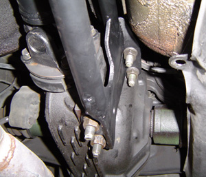
...Accessing the LS1's oil galley is easiest using the removable plate located on the left side of the oil pan, just above the oil filter (drilling and tapping is necessary) called the "oil pan cover". In order to get the rather large RX-7 oil press sending unit away from the LS1's exhaust, it is necessary to use a combination of fittings, such as the 2 "street" elbows shown in the pic, to allow tucking the sending unit back in next to the block. We prefer to use steel fittings, available at a hydraulic supply shop, as they are stronger and will better resist the increased vibrations of a longer multiple fitting setup.
...Remove the cover plate from the pan.
...Clamp the plate in a vise, using wood to protect the aluminum. Be careful not to place too much stress on the cover, which could cause it to crack.
...Drill a 1/32" hole into the cover as shown in the pic.
...Tap the hole to 1/8" NPT
...Carefully clean the cover block to remove dirt and machining debris.
...Using teflon tape on the threads, assemble the fittings and sending unit onto the cover block as shown in the pic. Test fit as necessary for a good fit.
...Re-install the cover onto the oil pan. Torque the cover bolts to 106 in/lbs.
 Installing LS1 Adapter Plates and Riser Mounts onto Engine...
...Carefully remove the forward/upper engine mount stud from each side of your engine block.
...Install the LS1 Adapter Plate into position over the 3 remaining mount studs, placing the tapered/countersunk hole over the hole from which the stud was removed (NOTE: there is a right and left plate). Thread the flat countersunk 10mm bolt (provided with your LS1 plates) in the plate's countersunk hole. Using anti-sieze, torque the bolt to 22ft/lbs.
...Install the original nuts/washers over the 2 rear studs.
...Install the rubber Riser Mounts onto the installed LS1 Adapter plates, with the lower center hole over the forward/lower LS1 block stud. Install the 2 supplied 3/8"x3/4" bolts into the rubber mount's upper holes. Torque all 5 bolts/nuts to 35ft/lbs.
...Right side LS1 plate and riser mount shown in upper pic.
...Left side of engine is shown in lower pic.
...Repeat for other side.
 Rigging Engine/Trans For Installation...
...For installation, the engine/trans should be rigged so that they naturally hang
level, or slightly tail down.
Dropping the Engine / Transmission into Position...
...(2) 7/16" x 3-1/2" long motor mount pin bolts
...(4) 7/16" flat washers
...(2) 7/16" self locking nuts
...Carefully lower the engine and transmission assembly into place. Line up and install the two 7/16" dia bolts and locknuts
through the engine mounts, pinning the engine mounts to the subframe.
...After the engine/trans are in their approximate position, support the transmission,
with a floor jack or jackstand, with the output shaft centerline about 6-1/4" below the top
of the transmission tunnel.
...Remove the engine hoist and chains.
...Tighten the mount-to-subframe pin bolts.
Torque Arm, Anchor & Transmission Crossmember Installation...
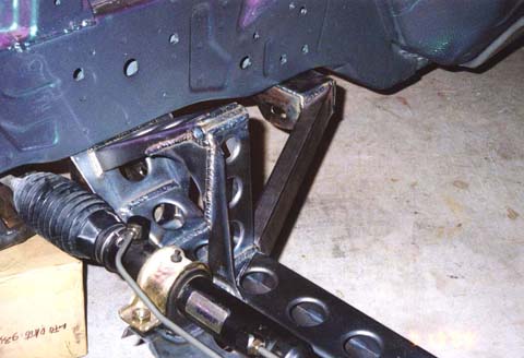
Torque Arm Front Anchor Bracket Installation...The anchor bracket bolts onto the side of the T-56, on the left side just below the
shifter. Tighten to 2 lower thru bolts and nuts to 35 ft/lbs. If your front anchor bracket uses an upper bolt that is threaded directly into the transmission, torque this short bolt to 20 ft/lbs.
 Installing Torque Arm / Differential Adapter Brackets...the torque arm differential adapter brackets bolt onto the existing differential
studs (formerly used to attach the PPF), using the origional RX-7 hardware.
Installing Torque Arm / Differential Adapter Brackets...the torque arm differential adapter brackets bolt onto the existing differential
studs (formerly used to attach the PPF), using the origional RX-7 hardware.
Installing / Pre-Adjusting The Torque Arm...the rod ends in the rear of the torque arm come installed and pre-adjusted for
proper pinion angle.
...The rod end on the front of the torque arm should be adjusted at the time of
installation, to a length that allows easy assembly of the eye bolt into the torque arm
anchor bracket attached to the left side of the transmission.
Transmission Crossmember Installation...
...Drill
...7/16" drill bit
...12mm wrench
...12mm socket
...14mm wrench
...14mm socket, rachet, and 6" extension
...9/16" wrench
...9/16" socket and torque wrench
4L60E/T-56 Transmission Crossmember Installation...remove the shield that covers the fuel lines on the left side/bottom of the
floor pan, where they pass by the rear of the transmission.
...Install and loosely bolt the rubber transmission mount pad onto the transmission.
...Loosely bolt the crossmember onto the rubber trans mount pad.
...Tighten all the installed trans mount and crossmember bolts. Properly positioned, the
crossmember spans the distance between the frame rails, leaving enough room for the fuel and
brake lines. Re-locating the fuel and brake lines is not required.
...Using a 7/16" drill bit, drill holes in the floor pan thru the (6) holes in the ends of
the trans crossmember (3 holes on each end), using the crossmember as a guide to locate the holes.
...Install the supplied bolt plates from the top side of the floor pan, thru the new
drilled holes.
...From the bottom side of the floor pan, bolt the trans crossmember onto the bolt
plate studs, using the washers and nuts supplied. Tighten the bolts.
...Remove the floor jack (or jack stand) from under the transmission. The
engine/trans should now be resting on it's own mounts, and supported by the chassis.
Checking Drivetrain Alignment / Clearances...
...The properly installed Chevy engine is centered in the car. The RX-7's rear
differential's pinion flange is offset 3/4" to the right of center. This is normal. The
engine/trans and the rear diff's pinion centerline should be parallel, but NOT concentric.
If the centerlines were concentric (exactly lined up with each other), the u-joints would
fail prematurely as they need at least slight internal movement to lube properly.
...The assembled driveline & slip yoke can be installed. The (4) pinion flange bolts should be
torqued to 43 ft/lb. At least 3/8" of clearance should exist between all parts of the
driveline / torque arm / transmission tunnel.
Be sure to double check clearances at the...
....Steering rack / oil pan
....EGR valve / firewall
....Harmonic balancer/ sway bar
....Hood / throttle body top etc.
....Alternator
2....Considerations & Requirements....
4....Engine / Transmission Installation....
5....Exhaust / Throttle Cable / Accessory Drive / Pulleys....
6....Cooling / Fuel Systems....
7....RX-7 Wiring Harness Connector ID and Circuit Locations....
8....Electrical System Modifications By Circuit....
9....Start-up / Troubleshooting....