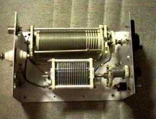
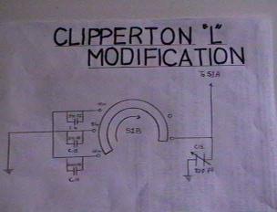
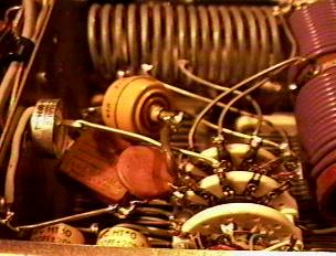
THE KK4TR/KN4LF ALL BAND 160-10 METER "L" ANTENNA & THE
CLIPPERTON "L" AMPLIFIER MODIFICATION. SEE DETAILS BELOW.
WITH THIS ANTENNA AND 100-125 WATTS I HAVE WORKED 48 STATES
AND 46 COUNTRIES INCLUDING AUSTRALIA, ON 160 METERS IN TWO
DX SEASONS. ON 17 METERS I HAVE WORKED ALL 50 STATES AND
107 COUNTRIES, IN ONE DX SEASON. KK4TR HAS WORKED 32
COUNTRIES INCLUDING AUSTRALIA, IN 2 MONTHS ON 160 METERS.
NOTE FOR SWL'S- THIS ANTENNA IN IT'S PRESENT FORM AND
LENGTH, MAKES AN EXCELLENT RECEIVING ANTENNA ON THE
LONGWAVE, MEDIUMWAVE AND SHORTWAVE BANDS. HOWEVER, IT'S
LENGTH CAN BE SCALED DOWN WITHOUT COMPRIMISING RECEIVE
PERFORMANCE.
AVAILABLE IN NEAR FUTURE- Detailed Discussion & Plans For:
Let me start off by stating that KK4TR and I don't make a claim that we have invented a brand new concept in vertical antenna design, though some of the combined design aspects of the antenna may be unique! We have simply identified the basic inherent weaknesses of your average city lot 1/4 wave inverted L and have devised methods to overcome these weaknesses. This antenna design is not a rival to a 4 square vertical array but will outperform your average backyard 1/4 wave inverted L or dipole by leaps and bounds.@- some slight increase in gain over a 1/4 wave. *- collinear antenna, 2 1/2 waves in phase. &- 4 1/2 waves in phase.
KK4TR and I are not Electrical Engineers, just two voracious readers of every book on antenna theory and design that we can get our hands on, some 50 years old. As avid antenna experimenters, we have put 2 years of field experimentation into this antenna design! Along the way we have come to the conclusion that antenna theory is just that theory, concepts not yet completely proven by controlled scientific experiment and not to be taken as gospel! We have also concluded that alot of sound basic antenna theory and design has been lost to time and/or watered down, to the point that many Amateur Radio Operators are grossly misinformed about the basics.
To be certain, an Electrical Engineer may come along and try to poke holes in some of the following antenna theory and concepts but one thing that can't be disputed is that the antenna is a proven informer! The average city lot backyard 1/4 wave inverted L suffers from several inherent weaknesses, high vertically polarized local noise pickup, absorption and pattern distortion of radiated signal due to surrounding ground clutter, high capacitive coupling signal loss between the antenna and your average poorly conducting soil conditions and low radiation resistance, a measure of antenna efficiency, due to the typically short (25-50 ft) vertical radiating element section of a 1/4 wave inverted L. With much effort the near field transmitted signal losses can be reduced to a point that you improve antenna efficiency to around 50% but the average backyard location makes it impossible to overcome signal losses in the mid field (1000-2000 feet) on 160 meters and signal losses in the far field (around 52,000 feet)(fresnel zone) is out of reach for all Amateur Radio Operators.
The 160 meter linear loaded 1/2 wave L antenna places the highest current point at the top of the support structure gaining the following advantages. The elevated highest current point of the antenna is above the majority of the local vertically polarized noise field. At my QTH my 1/4 wave inverted L noise level was always S9 to +5 over. With my 258 foot 160 meter linear loaded halfwave L, the noise level has been reduced to S2-3. Of course the actual amount of noise reduction will vary from QTH to QTH. Another advantage of elevating the highest current point is, reduced to nearly eliminated radiated signal absorption and pattern distortion, away from omnidirectional. In a sense you can say that the highest current point is getting a better omidirectional look at the radio horizon.
Another advantage of elevating the highest current point, is the reduction of capacitive coupling signal loss between antenna and ground and gaining the advantage of laying down l ess ground radials. Logic dictates that placing distance between the highest current point of the antenna and ground, reduces the coupling losses. The agreed upon standard for number of ground radials for a vertical antenna is 120 1/4 waves but you see a rapidly diminishing point of return after 16-20 1/8 to 1/4 wave radials. An alternative to ground radials is an eleveated counterpoise, which will be covered further into the text.
Radiation resistance, which as stated earlier is a measure of transmitting antenna efficiency is obviously a very important variable, basically the higher value the better. A 1/4 wave inverted L with a vertical section of 50 feet, will have a very low radiation resistance, around 15 ohms (very inefficient), increasing to near a theoretical 36 ohms as you approach a vertical length of 1/4 wave. Take this 36 ohms of radiation resistance and couple it with a poor ground radial system and you still have a very inefficient signal radiator.
There are several methods that can be employed to increase radiation resistance and henceforth transmitting antenna efficiency, excluding the laying out of dozens of ground radials. One is to raise 4 ground radials into an above ground counterpoise system. Four 1/4 wave wires approximately 15 feet off the ground, can rival 120 1/4 wave radials on the ground, as far as transmitted antenna efficiency goes but not necessarily concerning absolute lowest radiation angle. Another is to lengthen the transmitting antenna. As mentioned earlier, in theory the radiation resistance measured at the end feedpoint of a 50 foot vertical section of an inverted L is around 15 0hms, a 1/4 wave linear loaded L is near 30 ohms, a 1/4 wave 36 ohms, a 3/8 wave 300 ohms and a 1/2 wave 1000 ohms, a very efficient figure indeed! Basically as you lengthen the radiating element the radiation resistance increases and it decreases as you shorten it, it also varies with the diameter of the radiator. Antenna input impedance varies according to where you feed it.
So that's it in a nutshell, the 160 meter 1/2 wave "L" overcomes all the inherent weaknesses of the average city lot backyard 1/4 wave inverted "L". Now let's discuss the benefits of using the 160 meter 1/2 wave "L" on 80 through 10 meters, as a multiband antenna. As the length of a transmitting antenna exeeds a fullwave on the operating frequency interesting things begin to happen. Gain starts to increase and the radiation moves inward towards the axis of the transmitting wire, versus the 90 degree broadside you see on a halfwave dipole. As the transmitting antenna continues to become even longer in comparison to the operating frequency, multiple lobes of radiation form on the wire in response to the numerous highest current points that exist. The following table lists by band the number of highest current points on the wire (1/2's), the increase in gain and the radiation angle with respect to the antenna wire axis, with 90 degrees being broadside to the wire and 0 degrees being off the ends.
258 Feet Long Sloping at a 45 degree Angle FREQ KC #1/2 Waves Gain(dbd) Rad. Angl
- 1845 1.01 0.0 @ 90
- 3888 2.14 0.5/1.9* 52
- 7225 3.99 1.3/3.0 & 35
- 10115 5.58 2.2 29
- 14263 7.86 3.0 24
- 18139 10.00 4.0 21
- 21338 11.83 4.8 20
- 24960 13.87 5.6 19
- 28400 15.73 6.3 18

| Search for the Album or Artist of Your Choice! |