Switch Diagrams
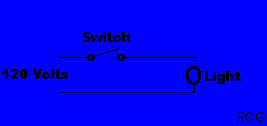
[ Simple Switch Loop. |||||||||
Three Way Switch. |||||||||
Four Way Switch. |||||||||
Double Switch with one feed. |||||||||
Split Receptacle. |||||||||
Emergency Stop |||||||||
Second Phone Line |||||||||
Stepdown and Stepdup transformers. ]Switch Loop.
This is the diagram for a simple switch loop.
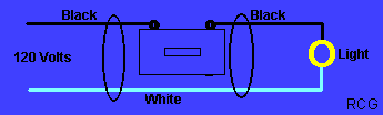
Switch Loop fed at light.
This is the diagram for a switch loop with the feed at the light. Please Note... The white wire marked (x) is a live feed from the switch loop, and must be marked as such.
[ Back to Top. ]
Three Way Switch
This is a diagram for a three way switch.


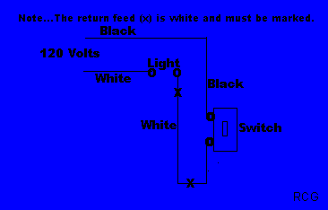
Three Way Switch with feed at light.
This is a diagram for a three way switch with the feed starting from the light. Please Note...The white wire marked (x) is a live feed from the switch loop, and must be marked as such.
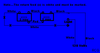
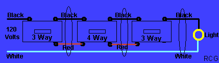
Three Way Switch with more than one light.
This is a diagram for a three way switch adding more than one light.

[ Back to Top. ]
Four Way Switch
This is a diagram to turn lights off and on from more than two areas.

[ Back to Top. ]
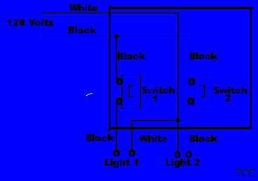
Double Switch with one feed.
This is a diagram to show how to turn seperate lights on and off from two seperate switches in the same switch box, with only one feed.
[ Back to Top. ]
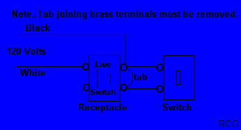
Split Receptacle.
This is a duplex receptacle with one half live and the other half on a switch. The tab joining the brass (live) terminals must be removed. The tab joining the silver (neutral) terminals must not be removed.
[ Back to Top. ]
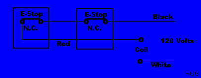
Emergency Stop
This is a diagram that uses emergency stop (e-stop) buttons to shut off a device or devices in case of an emergency. The switches for this diagram are of the manual push-pull type. When the button is pushed in the circuit remains open. When the button is pulled manually the circuit is closed.
[ Back to Top. ]
Second Phone Line
The Phone junction box is usually located on the outside of the house or in the basement. The green and red wires are for the main line and a second line is usually black and yellow.

[ Back to Top. ]
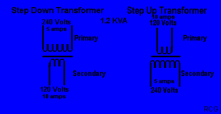
Step up and Step down Transformers.
The transformers below are rated for 1.2 KVA. to show the amperage change with different voltages. The advantage of the 240 volt 5 amps is that it will allow smaller sized wires to be used than the 120 volt 10 amps.
[ Back to Top. ]

[ More Three Way ||||||||| Electrical Tables ]