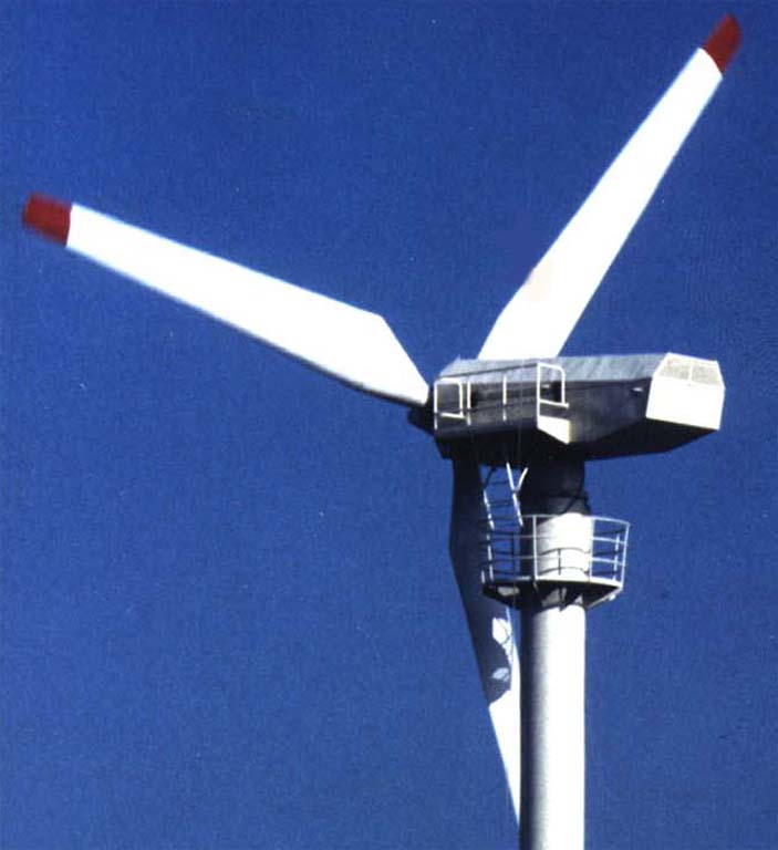
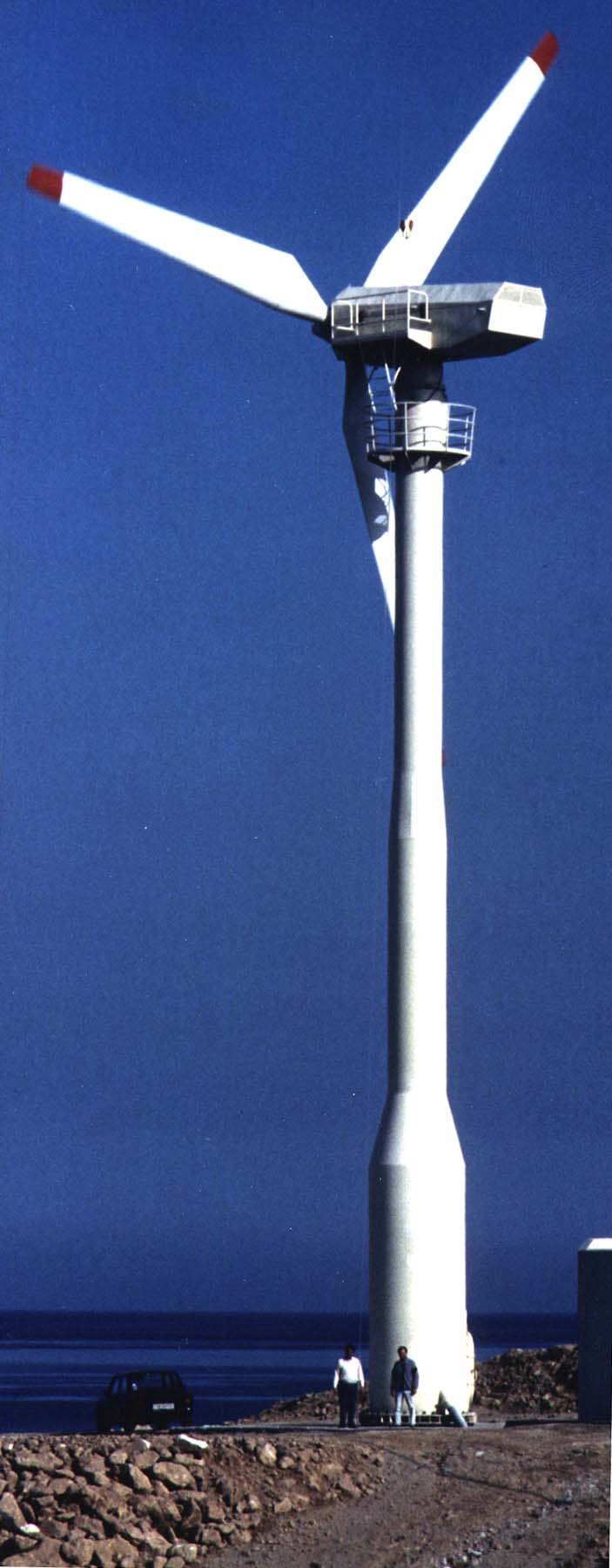

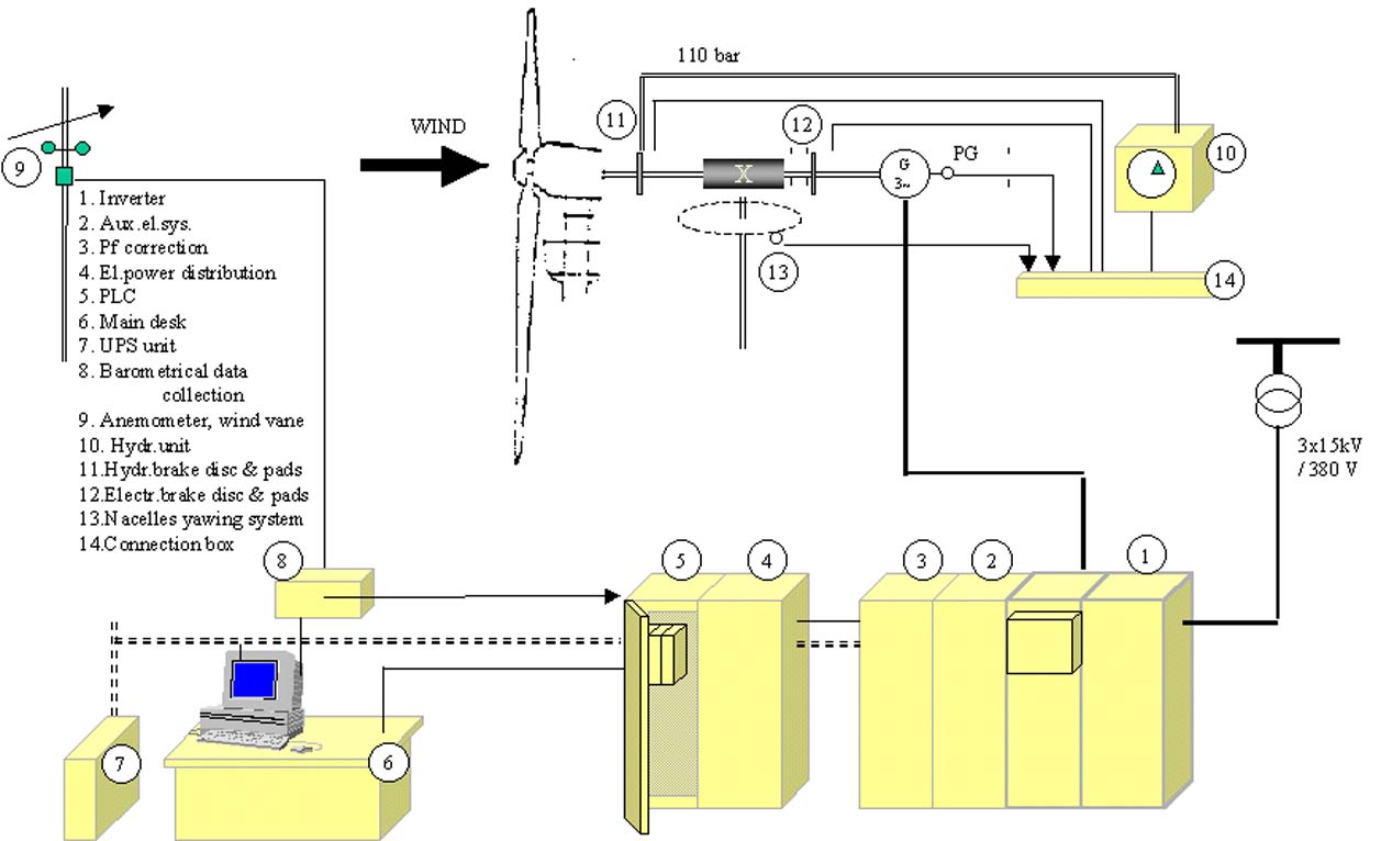
Fig.1 View of the nacelle Fig.2 The whole unit
The Picture 1 shows a view of the nacelle along its vertical plane of
symmetry.Fig.2 shows the whole unit and
a part of the room where the electrical-electronic control components
are installed.
The electrical panels, the main desk, the P.C and a UPS unit
are housed in a room besides the tower.
The main dimensions and the operation characteristics of the mechanical
components of the unit shown in Fig.1 and Fig.2 as well as of the electrical-electronic
equipment are as follows :
|
The rotor is an up-wind 3/fixed blade type of a 20m diameter, its axis being at a 24m height. The blades (type WPX20) are of the firm AERPAC (Netherlands).The rotor hub is of special cast iron GG40.2. It follows the hydraulic low speed shaft disc, 914 mm dia. X 25.4 mm of special cast iron fixed between the flange of the rotor hub and the flange of the low speed shaft of the unit. The latter is of 31 NiCr 14 alloy steel. It has a total length 1580 mm and a diameter of 240 mm to its front bearing (spherical roller bearing type), which is then reduced to 180 mm and to 160 mm at its rear bearing (paired face-to-face bearing). |
| The gear box of the USA firm BYRNE GEAR CORP., is a 2 stage planetary
type, (size
1500-20000) of 1:26 speed ratio, connected to the main low speed shaft
with a flexible coupling,
Citroen -Winflex type, size 28T. |
| The generator is of squirrel cage type, 3-phase, 380 VAC, 175 kW at
1520 RpM, of the firm ABB.
It is connected to the gear box high speed shaft trough a second flexible
coupling on the
front part of which is fixed the electrical fail-safe brake disc (515 mm diameter X 12.7 mm). A pulse generator placed on the rear shaft end of the generator gives its speed at any moment and for safety reason, a centrifugal switch for emergency stop situations if an over speed condition occur. |
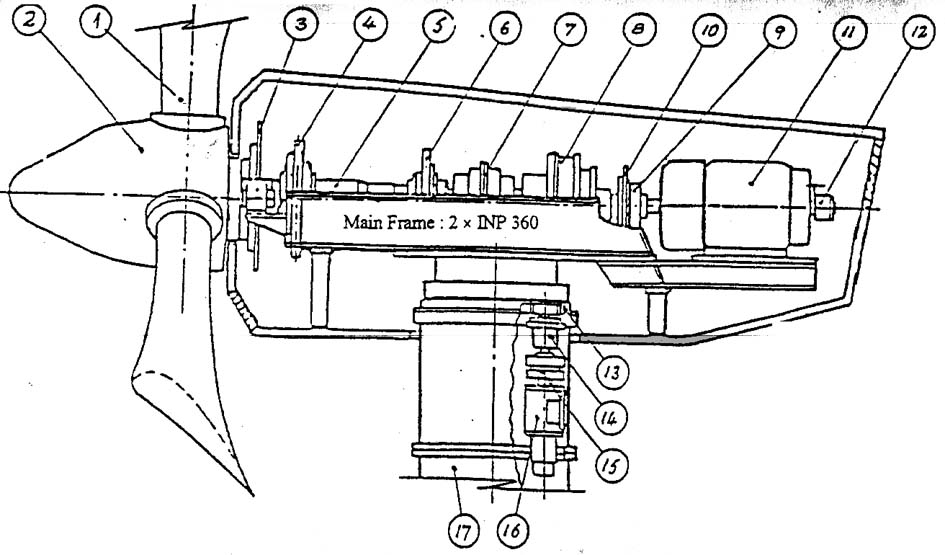
Fig. 3. OA 100 (100 kW) . Nacelle assembly
| An inverter AC/DC/AC current source type of 6 and 6 thyristors,
(ABB Veritron 144 kW, 315A ).
The inverter is followed by the necessary electronic equipment for the regulation of its programed operation and safety conditions. There are also a power factor correction unit with harmonic filter and a multimeasuring instrument type Dranetz 808. |
| A programmable logic controller (PLC), Siemens, S5115U, which acting on the inverter electronic unit that controls the frequency of the generator AC circuit by changing also its AC voltage, enables the generator to run at programed variable speed. |
| A UPS unit 5 kVA ,220 V, 50 Hz, single phase, to supply the PLC, the
electrical fail-safe brake and the sensors of the unit .
The UPS keeps the control system and, the hydraulic brake and the yawing motor in operation for emergency reasons when a network error occurs. |
| A main desk for the manually operation of the unit and checking the
operational condition of its components.
Also it will be used by inspection and correction of parameters inserted to the PLC, since the unit OA100 is a prototype model under test. |
| Sample |
|
|
|
|
This page has been visited
times.