Disclaimer: The information presented on this page is intended for people of 21 years of age or older who have a good working knowledge of electrical and electronic safety. The author is not responsible for any loss of any kind brought about by using the information given.
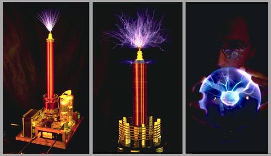
Tesla Coils are air-cored resonant transformers which generate very high voltages at high frequency. They can be used to produce very long sparks, and have been used in research and for special effects in films and at social events. A basic Tesla Coil setup is shown below:
The setup consists of a high voltage AC source, Tr1, which is typically a neon sign transformer powered from a domestic mains supply. This gives a typical output at the secondary of 6 to 15kV, at a few tens of mA and 50 or 60Hz frequency. For a neon sign transformer, the secondary is often centre-tapped. This centre tap is grounded. The a.c. current charges a primary tank capacitor C1 through two safety chokes L1 and L2. The capacitor C1 is of such a low value that during one half-cycle of the 50/60Hz a.c. it will charge to a high enough value that the spark gap g1 will break down. During the discharge at g1 the capacitor C1 is effectively 'connected' to the Tesla Coil Primary L3. The parallel circuit of C1 and L3 (referred to as the Primary Tank) then ocillates or 'rings' until losses dissipate all of the energy. The frequency of oscillation is much higher that the mains frequency, and at this high frequency the chokes L1 and L2 are effectively open circuit. This cycle is repeated on the next mains half-cycle, so that the gap g1 discharges at 100 or 120Hz. L3 and L4 form the air-cored Tesla resonator. L4 consists of a large number of turns of wire, one end of which is grounded, the other of which is connected to a terminal (spherical or toroidal), trm1. The terminal acts as one plate of a capacitor, earth acting as the other plate. This 'stray' capacitance is represented in the above diagram by C2. The combination of L4 and C2 form a similar tuned circuit to the combination of L3 and C1 in the primary circuit. The resonant frequency of the primary circuit is arranged to be the same as the resonant frequency of the secondary circuit. The oscillations of the primary cause the secondary circuit to resonate in sympathy. A very high voltage thus develops on Trm1. Whilst L3 and L4 do behave in some ways as a step-up transformer, it is the resonant effect which contributes most to high voltage seen on Trm1. During operation it is possible for discharges from Trm1 to 'strike' the primary L3. If this high voltage spike were to reach the transformer Tr1 it would be very likely to destroy it. So the combination of L1 and L2 help to filter the voltage spikes, and the 'safety gap' sg1 will fire to dissipate any residual voltage spikes. The high frequencies of oscillation of L3 and C1 can also lead to high dielectric dissipation in insulating materials. As Tr1 is usually only designed to operate at 50 or 60Hz, the high frequencies of operation could cause its insulation to fail. L1 and L2 also help to eliminate this effect. L1 and L2 are typically 2 to 10mH though values up to several hundred mH have been used. Ferrite cored or air cored construction can be used, but a resistor is sometimed required in series with air-cored chokes due to the high Q. It is possible to operate the above circuit with g1 and C1 interchanged. The general consensus is, however, that whilst g1 fires in the above circuit, the radio frequency currents in C1 and L3 cannot work their way back to Tr1 (g1 acting as a short).