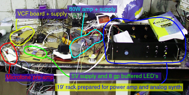
Lately I've been able to start building some of the equipment I had
in mind, to find out what works and what doesn't (thus far everything
according to my thoughts), and to present working prototypes to generate
funding and/or further business activities.
This page has been visited
times

In fact an additional tweeter is shown (the little cone in the broadband
has an irritably directional high response), the broadband is in the same
position as in the other pictures. In fact the bass response was quite
acceptable (30Hz resonance), albeith not very tight.

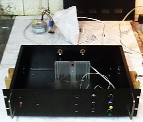
The rack now hold space space 10 pots with enough room to access them
comfortably without twisted fingers, and obviously has a power switch.
Currently, the pots are screwed directly in the front panel, which requires
knobs with a rim that covers the nut, which I currently didn't afford.
A alu U-profile behind the frontplate could solve this as well. The advantage
of this design is that everything excpet the Euro power cord connector
only need simple round holes, so produciton with low-cost tools is fairly
easy.

This amp costs about $8 + maybe another $5 for some trivial parts, and a heat sink, and a heavy power supply (about $50 dollars for 150 Watts or so, non-industrial prices).
The Amp's current supply transformer and rectifier + Elco's is shown in the upper left corner below, 2x26 Volts, 3.3 Amp, with room to grow.
Here, I've used a 4.7uF capacitance as a very basic seperation filter (cutoff about 4kHz) for the tweeter, and the other speakers are simply put in parallel (all are 8 Ohms), limiting the total power.
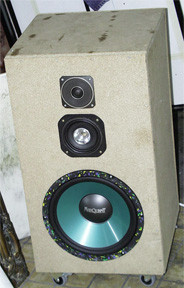
Overall, it sounds OK, I used it with moderately high volumes in a tiled basement, and it cranks out very clear, distinguised, non-boomy bass lines, fairly clear mid, and high as described above. Pleasurable listening experience, I need to try it in a 'living room' situation, and preferably stereo fashion to judge it better. Certainly beats all the consumer hifi equipment I've recently heard.
Oh, I should add it currently 'pumps', that is at higher power you can probably blow out a candle with the air leaking out some holes. Some silicone-kit will solve this, and the resulting bass response, assuming I can indeed drive the woofer at about three times current power (which allready is pretty loud, even playing music with non-forgiving basses), the bass end is definately up to acting as a PA system. Considering this design, including wood and amp cost me under $150 (non-industrial proces), and not too much work, that could be interesting.
The tweeter should preferably be replaced by a higher-power and preferably a bit more clear version, the broadband ($20) could act as a squaker.
I've currently made all speakers seperately driveable, and used a single 1.5 sq mm cable jack-ed into the 19 inch rack.

A set of wheels completes the prototype. Now some paint, or preferably a rugged coating (plastic, maybe metal edges). The mbf itself looks ok though.
Considering the speakers are real low cost, I think with better damping material, an air-tight cabinet, and active filtering / seperate amps, it will sound even better.
I've included detailed schematics of both the VCF, the VCO, and the exponential converter, and even an accurate SPICE electronic analysis in my pages on synth design.
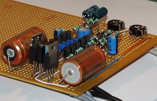
The above picture shows the integrated 2x12V supply, fed through a simple AC wall wart.

Thus top view contains a legenda to the parts of the filter prototype.
The 64k question: does it work ?
Yes, it does. It sounds pleasing, fat, versatile, has at least 20-20k Hz cutoff range, doesn't badly noise or hum (depending on distorion figures, this is open for some more measurements), even with a lot of resonance, and self-oscilates nicely, except that in the lower frequency range, a lot of feedback is needed fot unity loop gain, just as in the original circuit. I've done an early (breadboarded) prototype where I worked around this by a pole in the feedback loop, which made things better, but I stuck with the original circuit for this prototype board, which is intended to hold the other circuits as well to form a self-contained euro-card minimoog. The essentials, that is.
Currently the exponential converter described on my SPICE pages (which only has some parts scaled as compared to the original) currently is still on breadboard, because I consider using the same cicuit as is used in the VCO for the filter, because it is probably more accurate over a larger range, and has a intrinsic input zero correction (minus an opamp offset voltage).
Judging by listening to easy to percieve octave intervals, the volt per octave accuracy is sufficient.
Feeding audio signals through this filter and fiddling with the cutoff
and resonance controls makes for very strong and good sounding filter wah's
and oumphs, and the resonance can accurately cut out single harmonics,
e.g. from a saw tooth. Fast changes in the cutof control give good chorussy
and rich synth sounds.