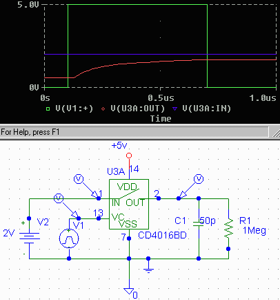

If we assume the on resistance is roughly 300 Ohm over the whole delta V range, and the propagation delay of some 10 nS is irrelevant, the RC time is roughly 300 times 50 10e-12 equals 15 nano seconds.
In the above graph, it appears that the 'on' resisitance is not realy the 300 it should be, because that would give a 99 percent (5 times RC) time of 5 times 50 times 300p is roughly .075 micro seconds after the 4016 20 nS switch delay (checked it on the datasheets. I measure roughly 2 micro seconds, a difference that cannot be accounted for by the (4 pF) paracitic capacitance, or by source resistance, which should be zero. Lowering the load resistor to 10 kOhm yields an output voltage of 1.2 V, so the on resistance is roughly 30 times too high.
After trying to accuse the simulator or part definition, I tried using a 10 Volt supply and logic input voltage, which does better justice to the internal mosfets' threshhold voltage, and voila: 100nS 1 percent settling time.
Minus the 20 nS propagation delay, and taking into account the coupling and especially the paracitic output C, this is completely in line with expectations. The ouput graph (not included here yet, I'll probably throw in some more opamps and stuff first) also shows a small 2d order (overshoot) effect, which I remember having measured also on a 4066 circuit, and which at the time puzzled me.
Some more on the subject
I've tried different input voltages as well, and found that all
works fine, except a 5.0V+-0.1 analog input voltage gives a
convergence problem (?!) probably a simulator specific voltage,
higher or lower works as expected:

In this image, I've indicated the 99 percent (should be 5 times Trc)
point, which is according to expectation, and added a .00001
indicator as well (roughly 1/pow(2,16)) to see when the convergence
should suffice for 16 bit accuracy. That should be roughly at
16 times the RC time, which is roughly 20 times 16 equals 320 nSec.
The measured value for that accuracy within rounding error
distance) is roughly 250 nS.
The last figures mainly arose out of curiosity for the 'probe'
capacity for graphing and interactive analysis, which seem
usefull.

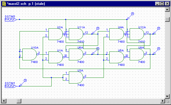
The resulting timing diagram, assuming a 5 megaherz clock and 20 nanoseconds delay per gate is:
