

 ONE METHOD OF ELECTROlYTIC REPAIR
I cannot accept credit for the text of this note, which I have turned into this page. I have managed to lose the original author's name, so I am not able to give him credit, where credit is due. If you are the author of this, e-mail me , and I will attach your name to this as soon as I can. I will know who you are the very moment you describe some of the things we did discuss, and some of the other work you needed to do to a radio.
This note describes my experience in repairing two electrolytic capacitors in an old radio. The process is time-consuming and rather messy, and you might not think it worth the effort. I simply (or simple-mindedly) treated it as a challenge and insisted on seeing it through. The results have been satisfactory. I must confess that this is the limit of my experience -- I've done only the two electrolytic, so I am not an expert.
Although the two electrolytic capacitors in this 1936 Coronado radio, Model 47R, did not match the schematic and so were likely later replacements, their design was probably the same as the originals. It seemed like a good idea to at least try to rebuild them so that the above-chassis view would be as we had found the radio, and also look quite similar from below. Modern electrolytics would easily fit inside these cans, but the tricky part would be to make the repair invisible.
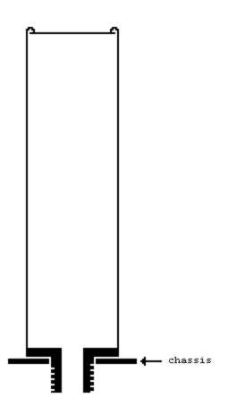
The bodies of these aluminum cans have thin cylindrical walls integral with a thick base, ending in a smaller diameter, stout, threaded extension that fits through a hole in the chassis. This extension is hollow to permit the passage of the wires. The top of the can is a thin circular plate of aluminum, held to the body by the rolled-over end of the can wall. A nut from below the chassis completes the mechanical attachment.
 Apparently the only satisfactory way to replace the can contents would be to go in through the base, as a correspondent (John McPherson, neutrodyne@isd.net) had suggested that "Unrolling the tops is not really practical, as the soft aluminum does not have enough resilience to allow the material to be rolled back into place." One possibility he mentioned was to drill out the inner diameter of the threaded lug to a size large enough to permit slipping a new capacitor inside. I decided to try taking out all the old contents, which eliminated this last idea.
A Dremel rotary tool with a fiberglass cut-off wheel (about 1" diameter) will cut through the aluminum base very nicely. Be sure to wear safety glasses or goggles, as a stream of aluminum dust and fiberglass shreds will be flying around. With some care, you can get a satisfactory opening in the base without cutting into the sidewall. Of course, the hole must be big enough so you can get the innards out and the new cap in. In my case, a pentagonal cut was the only reasonable option, given the sizes of the parts and tools.
Once the cutting is done, the lug should come away easily.
1) Remove the paper label if you want to save/reuse it. You can try to soak it off. That option didn't occur to me, and I was pleased when my labels came off fairly easily after I heated the caps to soften the contents.
2) Extracting the contents -- You could dig that stuff out with a small screwdriver or ice pick. That's how I started, but eventually I resorted to standing the cans on their tops on an old metal cookie sheet, baking them at 300 to 350 degrees F for as long as needed. Do it very late at night or very early in the morning when the family is still asleep so they won't complain about the smell. Handle carefully. Much of the content should come out easily when you pull the wires, but you may need to reheat a few times to get the remains out in stages.
3) When the can is reasonably clean inside, you can clean the outside with whatever mild abrasive you prefer; it should shine up nicely.
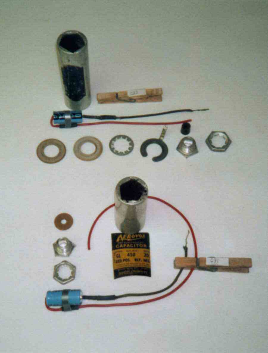
4) Now it's time to put it all back together. In the picture below, the two now-empty cans are shown along with the new caps and miscellaneous hardware. The clothespins carry small labels indicating the part numbers keyed to the schematic diagram. [Not really necessary for the electrolytics, but useful for the small paper/wax caps that I also reworked -- the clothespin is strung on a horizontal wire, suspended from an oven grate, and the pin holds onto a capacitor lead.] The spaghetti and shrink wrap on the cap wiring simply insulates everything from the metal can. Notice that I erred in buying axial lead caps, the other type would have been easier to use.
 It is now a simple matter to suspend the new cap into the can and pour in melted candle wax. Some points to consider:
(a) A wise worker will make an electrical check of the capacitor at every stage of this process. Make sure that your multimeter still proves that the lead wires still connect to a capacitor, and that both leads are isolated from the can. This assembly procedure is reversible, but you don't really want to do it twice.
(b) Pour in a modest bed of wax so the cap doesn't touch the can's cap.
(c) Center the new cap carefully in the can so the leads can come through the lug without too much bending.
(d) Make sure that any wiring joints will be deep enough in the can so that they won't interfere with the lug or, especially, any grommet that fits in the lug. See that little black thing beside the lug in the upper layout?
(e) Fill with wax almost to the top. You need enough space at the top for the lug to fit back in and make a level shoulder. If the lug stands too far out from the can base, the can will sit a bit high off the chassis; if the lug sits down inside the hole, then the mounting nut will stress the joint that cements the lug to the can base.
Now to seal it up. First, check it again with your multimeter.
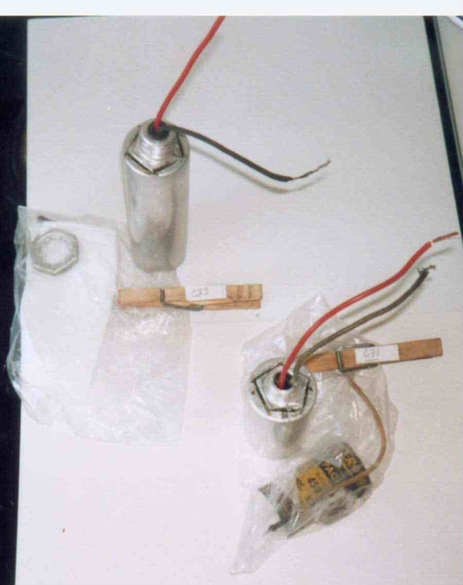
The next picture shows two caps ready for the final stage.
 I used a product called Epoxsteel, made by Bondo, an easy to use two-component epoxy containing steel powder. Mix together equal amounts of goop from the two tubes and apply. The mixture is somewhat viscous and sticky. I forced the mixture into the gaps from the outside, then tried to make sure that the lug would sit level and even while the Bondo cured. One can came out just fine, but the lug on the other can was tipped by about 5 to 10 degrees; to make that can sit vertical, I had to shim one side of the can base on top of the chassis. This second cap could be cut apart again and fixed, but I have not yet chosen to do so.
This Antique Radio Webring site owned by
John McPherson.
Random Site [
Previous 5 Sites
|
Previous
|
Next
|
Next 5 Sites
|
Random Site
|
List Sites
]
Important
notes:1) Images on this site are copyrighted, and those that I did not create, I have recieved permission for their use.
Any image inquiries can be directed to me via the e-mail buttons.
Thank you.


