INDIA

|
INDIA |
|
Model: Industrial Robot
Modeller: Shailendra Singh, Bombay
Notes: The model is a freelance design of a modern industrial robot used in industrial applications. Apart from a 360º rotation of the main boom on a thrust bearing, the most interesting feature is it's movement on horizontal and vertical axes, both controlled by linear actuators.
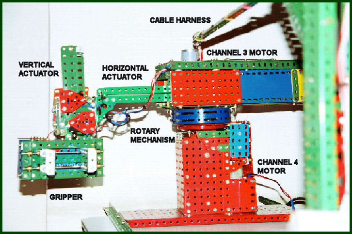
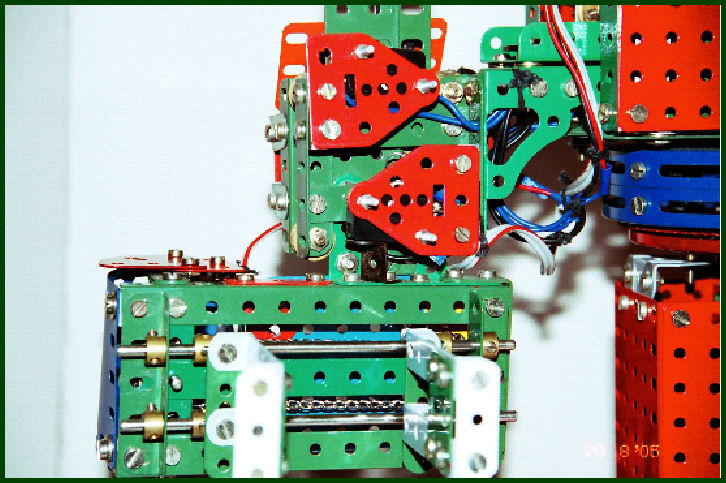
General view of the model
The Horizontal Actuator consists of two 25-hole Channel Girders [1x3x1] joined back-to-back with intervening spacing washers. A 12-½” Rack Strip bolted to it's inner side with spacing washers. A heavy duty 12V DC 10 RPM geared motor mounted vertically carries a 19t Pinion meshing with this Rack Strip (Channel 3). The girder assembly slides on rows of ½” brass Pulleys without Boss mounted on the inside of the long hood using various Strips, Angle Girders and spacers for smooth carriage. The Channel Girders and Rack Strip are mounted at right angle to the Channel 3 motor. This design helps in preventing the natural bending moment of the Channel Girders and provides enough strength to it so as to successfully carry the weight of Vertical Actuator (Channel 2) and Gripper (Channel 1) mechanisms attached to the free end.
The Vertical Actuator consists of two 13-hole Flat Girders bolted together with a 6-½” Rack Strip laid out in a manner similar to the Horizontal Actuator. A heavy duty 12V DC 10 RPM geared motor has a 19t pinion meshing with the 6-½” Rack Strip for movement (Channel 2).
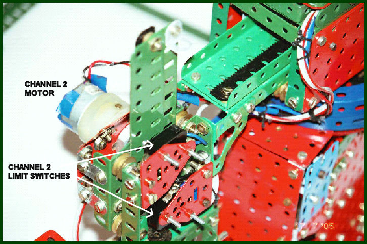
Both the linear actuators are protected from ''over-stepping'' in both directions by fitting limit switches which cut off the power supply to the motor when the arm reaches its limiting position. This is essential to protect the motor gearing from being damaged. The limit switches are having Silicon Rectifier Diodes 1N4007 attached parallel to the switch contacts to facilitate reverse feed, when the switch blocks normal supply.
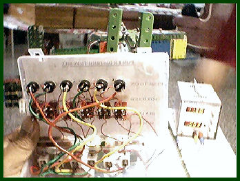
The Horizontal Linear Actuator assembly is fitted with a hinged lid which can be opened for viewing the internal circuitry by pulling out the circular steering wheel visible in the image to the left below. On the Inside is also visible the Limit switches and diodes.
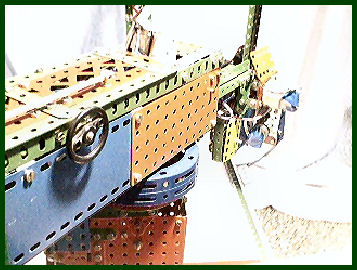

The entire boom assembly is mounted on a 4” Ball Thrust Bearing with a 20DP Toothed Race. The 360º movement is controlled using a 1”x 20DP Pinion as the driver. The drive motor is a 100 RPM 12 V DC geared motor, whose speed is further reduced using two stage gearing in the central column of the robot (Channel 4).
The Gripper consists of a pair of Sprocket Wheel and Chain assemblies. The two chain drives have opposite movement for moving the Gripper hands towards each other and away. The drive is from a 12V DC 16-RPM geared motor (Channel 1) The Gripper hands are mounted on Short Couplings that slide on a pair of 5-½” Axle Rods. The Short Couplings also have Long Threaded Pins screwed opposite to the hands. Cord Anchoring Springs fitted to these are then wire-wrapped on the Chain.
Power is supplied from a 2A DC regulated power supply where both voltages and currents are continuously monitored on digital panel meters and controlled using both coarse and fine adjustment potentiometers. The power supply is protected against over voltage and short circuit. The ultimate power to the four motors is controlled from a power distribution box. The box has directional control switches as well as push buttons for operation. This box also has a USB connector for connecting it to a PC for software-controlled automated operation of the model.
![]()