Compressor
Operation.
A compressor consists of a series of stages with each stage comprising of a row of stator and rotor blades. Unwrapping and laying the rotors and stators flat produces a series of airfoils to form a cascade. Each cascade passage acts as a small diffuser and produces a pressure rise. The rotating blade row exerts forces on the fluid moving through it increasing its angular velocity. By doing work on the fluid it changes the fluid enthalpy, with simultaneous changes in pressure. The following stator decreases the angular velocity resulting in an increase in pressure and sets up the flow for the following rotor.
Compressor Losses.
This changing axial velocity causes the airflow stream to have a downward flow, forcing the stream tube to spiral through the compressor. The changes in axial velocity with radius in the stream path set up viscous shear forces between the fluid stream tubes causing losses within the system. The radial and axial velocity is at its lowest at the hub producing further shear forces in the fluid, greater tapering of the hub increase these forces. At the blade tips where the axial velocity is greatest tip vorticies interact with the casing boundary layer causing shear and turbulent flow, further increasing the pressure losses. In the ideal flow these shearing forces are not accounted for. The rotor blades are twisted to maintain an even workload over the compressor as the radial velocity increases with compressor disk radius. Variations in this workload cause pressure differences along the blade surface. High pressure is then attracted to the lower pressure causing secondary flow. The blade profile determines the positioning and magnitude of shock waves on the airfoil sections.
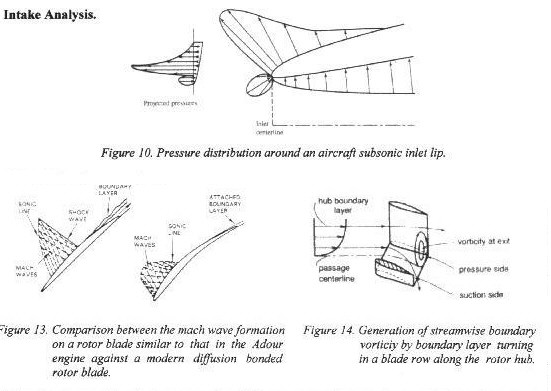
The Adour blades are of circular arc camber design; the camber follows the path of a circular arc drawn through the
center line of the blade. This design causes sharp oblique shock waves to attach to the blade convex pressure surface and the leading edge. These shock waves interact with the adjacent blade concave surface producing pressure losses. Changes in the carefully designed profile caused by erosion further increase these losses and can induce boundary layer separation. A build up of dirt on the concave surface and aft of the leading edge of the convex surface will cause further boundary layer separation. This build up is a common accurance on Adour compressors entering the engine bay. Reference (2) states that this build up of grime can cause efficiency losses of between 6% to 8 % and so increases in SFC. Also ingested dirt, smoke, or atmospheric dust is centrifugicaly spun towards the casing where it erodes the casing and increases blade tip clearance producing greater tip wakes. These tip wakes form vortices when the two different pressures meet which spiral of the trailing edges causing turbulent flow.
It has been known that a well-cleaned LP compressor can increase the thrust by 100 lb. Practical tests of this theory proved to be hit and miss. Completely new compressor assemblies were used in one test and still comparable results were obtained. The blades as well as the complete compressor assembly are lifed items and so old components with low life are replaced by new. This method reduces the likelihood of failure through preventative maintenance as well as ensuring compressor degradation is minimised. Although a compressor with high hours will show slight losses this does not seem to contribute to a substantial loss in thrust, as the thrust is still low with new compressors.
