
----Tutorials----
-Terrain's-
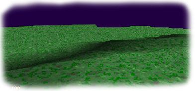
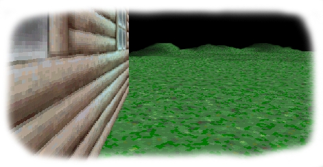
Like
my valley up above? I did it in under ten minutes!
NOTE: To instantly view an image full size just click
on one after all the images are done loading. The images
may appear to load slow but they are just scaled smaller to fit this page.
This tutorial will show you how to successfully landscape
your game. If you have never created landscapes in the GCS before then
continue with this tutorial, after the tutorial if you want a more advanced
explanation scroll to the bottom of this page for the instructions from
the 2.0 manual. 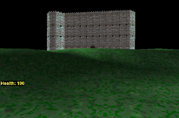
Making a landscape for your level is surprisingly
easy. In fact it's so easy we don't even need a download section for them,
but we have one any way for your convenience. Basically the colors in a
simple VGA image tells the engine how to draw the floor. First just open
up GCS paint from the paint icon in the DOS level editor. Create a new
64x64 image. Now take a light color- lets work in shades of white. Take
the brightness shade of white you can find and draw a small circle.
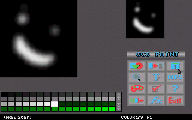 Draw
a few more. When your done drawing extremely blur the image and save it.
Make sure that around the edges of the image the color is pure black otherwise
the floor panels won't match up correctly in the 3D world. Put the image
in the floor/ceiling directory if it wasn't saved there originally and
ditch the old DOS editor by testing your level, you won't be needing it
again .
Select "Edit Extra Data" when the extra features editor
opens. When the Floor and Ceiling window comes up create a floor panel
and select "Texture Map". Select the texture you want on the panel. Make
sure the floor panel is still selected and then click on the "Terrain Map"
button right beneath the texture one. This is where you select the height
map for the selected floor panel. Now you have to add your image to the
library. Do so like you would any other image. Shutdown the Window's engine
and return to the dreaded DOS editor. 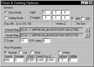 Don't
worry, were just going right back to Windows. So select "Test Level" and
once again "Edit Extra Data". Pick the panel you want the terrain to apply
to. Click on "Terrain Map" and choose your image. Also change the 0 Pt.
Index box to 0 instead of the default 32 this way the terrain will not
go below what I call the "virtual sea level". Close the editor and save
your changes. Now test your level. And that's how you create a basic terrain.
That should of been a snitch, and if it wasn't then email me. Now read
the 2.0 manual instructions on making terrain's to learn more advanced
features.
.
.
.
.
.
.
.
2.0 Manual Instructions
Floor & Ceiling Options: Terrain Map
This option controls terrain mapping for the selected
floor or ceiling panels in which .VGA images are used to form surface height-maps.
The first step would be to create a 64x64 .VGA image with a palette shaded
from dark to bright. The box labeled '0 pt' determines the palette index
number which will represent the starting Z height. For example, using the
default value of 32 means that any color value less than 32 in your artwork
will lower the floor/ceiling vertexes, while a value greater than 32 would
raise them. You may adjust this to any value between 0-255. Once you have
decided your '0 pt' you should fill your image with this color index, then
begin shading the image as you see fit. The box labeled 'Scale' determines
the scale factor of the shading in relation to the Z offsets. Thus increasing
this value will produce more dramatic differences in height while using
low values results in more subtle changes. After you are satisfied with
your image you must save it in your project's FCLIB directory and import
it into the .VGA list as you normally would a floor or ceiling texture.
To map this image to a floor or ceiling tile, simply click on the desired
floor or ceiling panels and press the button labeled 'Height Map'. This
will take you to the .VGA image list where you select your height-map image.
Locate and select the image and press 'OK'. You should then see the description
of the image in the text-box next to the 'Height Map' button. You must
then restart the editor for the changes to take effect. Now when you go
test your level, the selected floor/ceiling area should be deformed to
the image map you created. You may need to experiment with the scale and
0 pt values and possibly the artwork of the image itself before you get
the desired effects you want.
You may create up to 64 different height-map images per level, though
any number of floor/ceiling panels may be assigned to use them. To remove
a height-map from a panel, click on the desired floor/tile and press the
'C' button located to the right of the height-map file description box.
Tips: This feature works best on large placements of floor/ceiling tiles
since the height adjustments occur at the vertexes, approximately 400 cm
apart. Therefore when shading your .VGA image try to avoid sharp lines
and single pixel details since the vertexes might miss them. Results are
generally best if you use the smoothing functions of the paint program.
Sharp shading or high contrast between neighboring pixels will create steep
slope effects, which may be visually dramatic, but will cause problems
in the collision testing of the player since floors/ceilings do not process
wall-bumping. In other words, the floor might be sloped so steep that it
actually resembles a wall in the game-world but it will not behave like
a wall or bump the player back; instead the player will ascend to the elevation
of the next point of the floor - even if that point is 2000 cm high!
A good way to circumvent this problem might be to surround the interior
of the base of such slopes with walls turned backwards and attributes set
to 'Dont Draw Backsides' so they will be invisible, thus creating a block
which would prevent the player from 'popping up'.
When shading your .VGA image it does not matter
which colors you use. The rendering only looks at the palette index number.
Therefore you should always set your palette shade range from darkest to
brightest to help maintain a visual reference to what the final rendering
will appear like. Also be careful when shading the outer edges of your
image since doing so will effectively raise or lower the outer edges of
your floor/ceiling tiles, making it difficult to match up properly to neighboring
tiles. It's usually best to leave the outer 2 or 3 pixels of the artwork
set to the '0 pt' color which would be the initial Z height of the tile
itself.
Terrain shading options
If every triangle of the terrain is displayed at
the same illumination, it is hard to see the bumps and dips. Therefore,
the terrain triangles are shaded according to their angle.
Since some terrain's look better with deeper shading, and others need only
very subtle shading, you can adjust this shading factor in floor-panel
dialog. A value of 1 gives maximum shading effect, and value
of 10 gives pretty miminal shading. You can go all the way up to
64, which would probably be such slight shading it would be unnoticeable.
_
<-Go
Back

