Industrial Automation
Telemetry & SCADA systems
A&B (G. Vassiliou) Ltd
has a broad engineering experience in the field of Industrial Automation .This refers to hardware as software for:
- Automation of Factory and Motor Control Centers
- SCADA systems
- Telemetry systems
PLC Automation; SCADA system example 1; SCADA system example 2; Top

PLC Automation for a Pumping Station
This Pumping station pumps water from a treatment plant to a remote reservoir.
The level of the target reservoir is received by a telephone line. Depending on the inlet flow to the pumping station, the level at the source and target reservoirs and the available electrical power, the system starts or stops automatic from one up to four pumps.
The pumps starts and stops with closed valves.
PLC Automation; SCADA system example 1; SCADA system example 2; Top
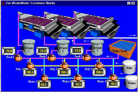
Example of Graphic Supervision of Treatment system with MX-SCADA
PLC Automation; SCADA system example 1; SCADA system example 2; Top
SCADA System of a Water Treatment Plant
The following SCADA system developed with MING was designed for a Water Treatment Plant. It consists of several Screen Pictures, displaying a part of the Plant’s Process Diagram.
The operator can toggle between the Overview Picture and the several Process Sub Pictures by moving the arrow of the mouse at a Diagram block in the Overview Screen and click on it with the left mouse button. By clicking on the Overview button at the Process Sub Picture the operator returns back at the Overview Picture.

Fig. 1: Overview Picture

Fig. 2: Process Sub Picture (Service Water Pressure System)
Alarming:
The small rectangular space at the bottom of the each screen is reserved for Alarming.
If an Alarm occur, the Screen Jumps immediacy to the Picture which visualise the Process Detail where the fault is registrated.
For example if the Screen is displaying the Overview Picture and the pressure of the Service Water System becomes very high, the screen jumps to the Service Water Picture. An example of the Screen is shown in fig. 3.

fig. 3: High Pressure of Service Water
By clicking with the left mouse button on the Alarm text in the Alarming section of the screen, or by pressing the Acknowledge key ‘F2’ the alarm is acknowledged.
By pressing the Alt key and M a small window occur as shown in fig. 5.
The operator can choose to enable or disable printing of Alarms; Audible Alarms and/or Disable all Alarms. If it is enabled it becomes red, if it is disabled it turns blue. In the above example the SCADA node is running, Alarming is activated, Audible warning is enabled, printing is disabled.
By clicking on a Alarm in the History Log (fig. 7) a individual Alarm can be disabled.
fig. 4: System Mode


