- Forward biased have current to cathode, Junction Field gets smaller, current flows.
- Reverse biased have current to anode, Junction Field gets larger, current flow stops.

| Semi-Conductors | P-N Junctions |
| Atom Structure | Diodes |
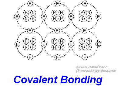
| Covalent Bonding | Transistors |
| Electron Flow in Semi-Conductors | Resistors |
| Ions | Capacitors |
| Electron-Hole Theory |


| Multiplier (Band 3) | ||
| Black | ||
| brown | ||
| Red | ||
| Orange | ||
| Yellow | ||
| Green | ||
| Blue | ||
| Violet | ||
| Gray | ||
| White | ||
| Brown | ||
| Red | ||
| Orange | ||
| Gold | ||
| Silver | ||


 , yay!