It should be emphasized that a turbocharger does not basically change the operating characteristics of an engine. A turbocharger is not a power source within itself. The turbocharger's only function is to supply a greater volume of compressed air to the engine so that more fuel can be burned to produce more power. It can function only as dictated by the flow, pressure and temperature in the engine exhaust gas.
1) Turbocharger Components
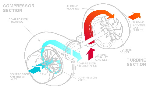
Expanded engine exhaust gas is directed through the exhaust manifold into the turbine housing. The exhaust gas pressure and the heat energy extracted from the gas causes the turbine wheel to rotate which drives the compressor wheel. Exhaust gas pressures and temperatures drop as they pass the turbine wheel and are then routed into the atmosphere.
The rotating compressor wheel draws ambient air through the engine's air filtration system. Its blades accelerate and expel the air into the compressor housing where it is compressed and directed through ducting to the engine intake manifold.
Each engine size and power output must be properly performance matched by the
turbocharger. Power output needs determine the amount of air pressure rise
required to deliver the proper volume of air to the engine. This is
accomplished by combinations of wheel size, wheel speed and housing size.
Turbochargers are composed of an exhaust gas-driven turbine and a radial air compressor mounted at opposite ends of a common shaft and enclosed in cast housings. The shaft itself is enclosed and supported by a center housing, to which the compressor and turbine housings are attached. The typical turbocharger can rotate at speeds of 100,000 RPM or more.
The turbine section is composed of a cast turbine wheel, a wheel heat shroud and a turbine housing, with the inlet at the outer diameter of the turbine housing. It is a centripetal, radial-or mixed-inflow device in that exhaust gas flows inward, past the wheel blades, and exits at the center of the housing's diameter.
The compressor section is composed of a cast compressor wheel, a backplate, and a compressor housing, with the inlet at the center of the compressor housing diameter. It is a centrifugal, or radial-outflow device in that the air flows outward, past the wheel blades, and exits at the outer diameter of the housing.
A turbocharger without the compressor and turbine housing attached is called a Center Housing and Rotating Assembly (CHRA). The center housing (bearing housing) supports the compressor and turbine wheel shaft in a carefully designed bearing system. The bearing system, designed for high speed, does not see heavy loading as with crankshaft bearings, but rather must delicately position the wheels as closely as possible to the contour of the end housings. Key to this positioning is the oil filling the clearances between the center housing bore, bearings, and shaft. This oil filled clearance is vital to a turbocharger's efficiency and longevity.

This Oil Flow Schematic describes how oil delivered from the engine's
lubrication system is directed by ports and grooves to the journal bearings.
Oil flows through the holes in the bearings to lubricate and cool the
bearings, bores and shaft journals. Oil is also directed from the inlet port
to the thrust bearing or through a passage in the backplate to the thrust
bearing. Oil drains from the center housing by gravity.
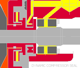
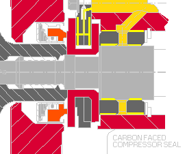
Seal systems separate the center housing from both the compressor and the turbine stage.
 |
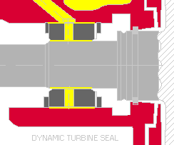 |
The seals restrict the oil from entering the compressor and turbine areas and reduce the flow of gases from those areas into the center housing. These systems may include piston ring seals, carbon and O-ring seals, oil slingers and labyrinth (threaded) seals to accomplish the task. The oil seals are activated when the shaft rotates and housing pressure develops
Various retaining rings and bolts secure or hold in place the rotating components. Thrust components maintain axial integrity. A shaft nut or threaded wheel is used to join the compressor wheel and the turbine wheel. The turbine and compressor housing are attached to the center housing and rotating assembly by bolts, V-band clamps and/or clamp plates, lockplates, and bolts.
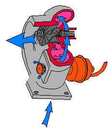
Swing valve, poppet valve, and wastegates are types of exhaust control devices which help control turbine speed which in turn helps to control boost. They are either integral to the turbine housing or are a separate device plumbed into the exhaust system as pictured below.
 |
 |
Actuators are connected directly to the compressor outlet or work in conjunction with the engine management system. Engine manufacturers supply specific information on waste gates because of their arrangement within the engine management system.
2) Operating Procedures
Years of experience has shown that the largest percentage of turbocharger failures are caused by lubrication problems such as oil lag, restriction or lack of oil flow and foreign material in the oil. The second largest percentage is caused by foreign objects entering the compressor and/or turbine wheels.
A turbocharger that has operated successfully is very unlikely to be found defective at a later date. Speed and temperature normally seen in turbocharger operation usually identify defects very quickly. Installation or engine system problems can also show up immediately upon replacement.
Good maintenance practices should be observed, particularly regarding air filtration and oil quality and filtration. These areas are important because of a turbochargers speed of operation. Proper operating procedures and preventive maintenance practices give good turbo service life and performance.
Maintenance procedures based on strict engine operating hours, vehicle miles, or calendar periods are often not practical to apply to turbochargers. This is due to the wide variation in lubricants and the operating modes and conditions to which they are subjected. In addition, since calibration and adjustment procedures cannot be performed on in-service turbochargers, and since lubrication is supplied by the engine on which the turbocharger is mounted, periodic maintenance in the usual sense is not required on a Garrett-type turbocharger, with the possible exception of occasional compressor stage cleaning.
For these reasons, preventive maintenance of a turbocharger consists primarily of ensuring that the integrity of the engine/charge air system is maintained and that the engine is not operated in a manner that is detrimental to the operation of the turbocharger and engine.
The vehicle owner should be encouraged to observe the following precautions to ensure maximum turbocharger service life:
- Operate the engine above idle only after normal engine oil pressure has been established. Revving the engine immediately after start-up can force the turbocharger to operate at maximum speed before the bearings can be adequately lubricated. A turbocharger running with insufficient lubrication can suffer some amount of bearing damage. Repeated occurrence may lead to premature turbocharger failure.
- Take steps to reduce temperatures and speeds from their maximums before shutting the engine down. turbochargers operate at speeds and continuous temperatures that are higher than most other machines. When an engine is run at maximum power/torque output, turbocharger speeds and temperatures are also at maximum. See Figure 17. Problems can be caused for the engine and more so for the turbocharger when the engine is shut off at this point. This may require operation at medium idle or at "light load" conditions while still maintaining full engine oil pressure and airflow over the cooling system. Following these guidelines will prevent prolonged turbocharger rotation without lubrication and the formation of carbon deposits shown in Figure 18 that can form as residual oil is decomposed in the bearings and center housing (heat soak-back).
- The turbocharger may need to be pre-oiled after an oil change or any service that involves oil draining. Crank the engine a few times before allowing it to start, then start the engine and allow it to idle for a period to establish full oil circulation and pressure before operating at higher rpm.
- At low ambient temperatures, or whenever the vehicle has not been used for a long period, normal engine oil pressure and flow is affected. Under these conditions the engine should be started and allowed to idle for a few minutes before operating at a higher rpm.
- Avoid long periods of engine idling. The combination of low-pressures in the turbine and compressor and low turbocharger shaft rotation speed may allow oil to seep past the seal into the turbine or the compressor. This will generally not harm the unit mechanically, but it may foul the wheel and cause complaints.
- Make certain that the entire engine lubrication system, shown in Figure 19, which includes the oil pump and general engine condition, as well as all passages and lines are capable of producing and maintaining needed oil flow and pressures.
- Make certain that the oil inlet supply lines and outlet drain lines are clean and routed properly. Oil feed and drain lines should be routed to minimize heat transfer from the exhaust manifolding and other high heat sources. Replacement of the oil supply lines is highly recommended as the lines often become clogged with carbon. If hoses are used, make certain that they have not hardened or collapsed and that the inner lining has not deteriorated and started to flake off. If metal tubing is used, make certain that it is not restricted or collapsed. Some oil feed hoses have reusable fittings that allow the replacement of only the hose. Verify that the fitting installation has been correctly completed and that there are no hose lining fragments remaining in the assembly.
- Gasket sealers, and seal tape have been found to cause problems when used on either turbocharger oil inlets or outlets. Problems develop when gasket sealer or tape is squeezed or extruded into the oil passageways as the connections are tightened. When these types of material enter the oil inlet, oil flow to one or more bearings will be blocked or interrupted. Oil flow and pressure can also force the material into the bearings where it will cause abnormal amounts of wear. On the oil outlet side of the center housing the deposits may extend enough to restrict the out flow of oil.
- Make certain that the lube oil is clean and at operating level. When possible, the oil filter should be filled with clean oil to minimize cranking time.
3) Major causes of damage
Because turbochargers are rotary machines that operate at high speeds and temperatures some of their failure modes are not readily apparent. Forces and frequencies developed in high speed machines often reach levels that are quite unexpected. The heavy damage often found is not in proportion with the forces that the unit sees when operating properly. A broken shaft or a destroyed bearing is usually not the defective part but rather the part that received the damage. Once the damage has been done, measuring or checking the parts from the unit in question will give little useful information. Examination of the areas adjacent to the journal bearing travel may allow the determination of the condition of the finish and dimension of the shaft journals and bearing bores before damage.
Bearings and seal systems that are appropriate for turbocharger applications share little with those used on crankshafts and other lower speed devices. In operation when all is well, the bearings are very lightly loaded. Together with the lubrication film the bearings delicately position the rotating group with the wheels held close to the end housings. Most primary causes of failures that are difficult to determine are those things that prevent the stable positioning of the rotors at speed.
Examples of primary failure modes are imbalance, incorrect dimensions, insufficient lubrication, foreign object damage, and operation at excessive temperatures. Examples of incorrect dimensions are parts that were not properly manufactured, incorrect parts for the assembly, and parts that have been damaged by foreign material in the lubrication or other causes. The longer a turbocharger has run, the less likely it is to be defective. High operating speeds tend to expose defects quickly.
When a damaged turbocharger is replaced, with little or no thought given to the cause of the damage, there is a recurrence of the failure resulting in extra down time and expense. Bear in mind that repeated "caused" damage (insufficient lubrication, foreign object damage, contaminated oil, excessive temperatures) may repeat itself in increasingly shorter periods. Identifying the difference between a product defect, which leaves nothing for the mechanic in the field to correct, and caused damage can reduce equipment down time.
Most turbocharger damage can be traced to one of a few basic causes:
Operational Temperature Extremes
Insufficient Lubrication
Lack of proper lubrication can ruin a turbocharger within mere seconds of operation. With shaft rotation speeds approaching 200,000 rpm in some models, all bearings must receive a supply of oil that can stabilize, lubricate and cool. When lubrication is slowed, stopped or interrupted for any reason, metal to metal contact first occurs at the journal bearings/shaft journals/bearing bores of the center housing. Without the oil, friction will generate enough heat to turn the shaft and/or thrust collar blue. (This bluing is often not as evident in units with liquid-cooled center housings.) The thrust bearing, thrust collar and/or backplate mating surface will also show signs of damage.
Once the bearings are damaged, "shaft motion" increases. Instead of rotating in a perfect circular motion, the shaft begins to orbit. As bearing clearances are enlarged, shaft motion becomes more intense, and damage accumulates. The center housing seal bores, shaft hubs, and thrust components (thrust collar, thrust spacer, and backplate assembly thrust bearing, as applicable) are damaged next. This additional damage, in turn, allows for more violent shaft motion.
After shaft motion reaches a certain point, the turbine and compressor wheels will contact their respective housings damaging the blades and possibly backing off the shaft nut. When blades are damaged by housing rub, the precise balance of the wheel/rotating assembly is destroyed, leading to even more shaft motion. The shaft may eventually break from a combination of motion stress, fatigue and destabilization (due to the original problem, insufficient lubrication).
Of course, if the turbocharger is taken out of operation when the problem first begins, the damage may not be as extensive as described. But given the immediate effect of insufficient lubrication, the operator may not be able to react quickly enough to prevent major problems.
When you are analyzing these problems, it is important to remember that when the unit has been damaged because of insufficient lubrication, damage begins at the journal bearings and spreads outward toward the wheels.
Foreign Material In Oil
Foreign material in the oil includes various sizes of abrasive particles, corrosive chemical compounds, and dilution by coolant or fuel. Foreign material in the engine lubrication system first damages the journal and thrust bearings. When foreign material in the oil is found to be the primary cause of damage, steps should be taken to identify the foreign material or eliminate its entry into the system.
Abrasive Particles
Fine abrasive contaminants will score and wear virtually every bearing surface. If material particles are large enough, the contaminate related damage is more confined to journal bearing outside diameters and center housing bearing bores because centrifugal force keeps the contaminants away from the spinning shaft.
Corrosive Chemicals
Corrosive chemical compounds alter surface finishes and clearances. When surface finishes are too rough, oil films are penetrated allowing metal to metal contact.
Diluted Oil
Diluted oil has its film strengths reduced and does not easily adhere to surfaces. The lack of surface adherence does not allow the shaft to be dampened and supported by its encompassing oil film.
Even premium oil will decompose if temperatures are forced high enough during operation or shutdown. When these temperatures reach the center housing the deposits will form throughout its interior. As deposits accumulate, oil passages become restricted which reduces oil flow through the unit, further elevating the temperatures aggravating the condition. Obviously, once the condition has started it cannot be brought under control without identification and correction of all causes. Concurrent with the build up of these deposits in the center housing, oil supply and drain paths are becoming restricted. These deposits migrate to fill much of the oil supply and drain lines. The granular carbon deposits, now part of the oil supply to the bearings, damages surfaces and increases clearances or accumulates on the bearing surfaces diminishing space for oil films to develop. All of these deposits alter the bearing system and prevent normal operation. Excessive bearing damage from foreign material in the oil will eventually lead to shaft motion and, finally, turbocharger failure.
Other lubrication problems - low oil pressure, wrong oil grade or oil not changed often enough, will eventually affect the turbocharger bearings as previously described.
When a foreign object enters the compressor or turbine the turbocharger will become affected very quickly. Upon close inspection you'll find that the damage can often be related to the type of material. Hard objects, such as bolts, valves or rocks, will break pieces from the blades or "machine" them down. Abrasive matter, such as sand or dirt, will wear-away the undersides of the blades and their edges. Soft material such as rags, will bend the compressor wheel blades backwards.
Any wheel blade damage can destroy the balance of the rotating assembly, which leads to shaft motion, loss of efficiency or noisy operation. When foreign objects strike the wheel, loads can be extreme. The loads can be high enough that catastrophic failures result.
Foreign object damage to the compressor wheel distributes damage relatively even to all blade edges. Foreign object damage to the turbine wheel distributes damage evenly to all blade tips.
After a foreign object has entered the turbocharger, be sure to check the engine for initial or resultant damage. And remember, if a unit has failed because a foreign object has entered the system, damage occurs first at the wheels and then spreads to the center housing and bearings.
Operational Temperature Extremes
Turbocharger damage can be caused by high temperatures during operation or after shutdown. Some types of damage has been discussed in the sludged center housing section. Generally, the source of heat that causes the problem comes from the exhaust gases. Elevated exhaust temperatures can come from incorrect engine air/fuel ratios, timing problems, restricted exhaust systems, malfunctioning exhaust oxygen sensor, or other engine control system problems.
Excessive exhaust temperatures can damage the turbocharger either directly or indirectly. With direct damage, excessive temperatures overheat the center housing and actually erode or distort the turbine housing material. Results of the distortion can be found on the turbine housing contour. Turbine wheel rub can result slowing shaft speed and aggravating the problem. Heat moves down the shaft from the turbine toward the compressor, damaging the journal bearings. Oil in the center housing cokes and builds-up deposits adding to the bearing failure process and finally leading to shaft motion. In the meantime, eroded turbine housing material may separate from the housing and become a "foreign object." Turbine housing cracking can also result from excessive exhaust temperatures.
Indirect damage from excessive exhaust temperatures occurs when the rotating assembly begins to turn faster than its designated operating speed due to the additional heat energy. If this happens, the compressor wheel may burst apart because of a single or repeated high stress load. The turbine wheel may burst apart because of the reduced strength from high temperatures and the elevated speed.
Also, the bearing system may become overspeeded. The point at which the bearing system overspeeds is determined by the oil temperature and quality as well as shaft speed and bearing clearances. The overspeed condition ruptures the oil film and allows metal to metal contact. Whenever catastrophic turbocharger failures occur, steps must be taken to remove all debris from the engine.
Hot Shutdown
Hot shutdowns are identified by extensive deposits of carbon and shellac in the turbine end seal parts and bearing system and may progress toward the compressor-side. In early stages of the failure, bearing clearances are decreased by the deposits. As the problem continues, the deposits break up, scoring and wearing the bearing bore, bearing, and shaft journal. The deposits form as oil decomposes, solidifies, and sticks the parts together. When the engine restarts there is no residual oil in the turbine end bearing and seal system.
Abnormally high operating temperature, unusually frequent shut downs at maximum temperature and inadequate lubrication are the things that, together or independently, can produce hot shutdown problems.
When failures initiate from manufacturing or material defects the
turbocharger is damaged quite differently than when damaged by the previously
mentioned failure modes. The damage is somewhat localized around the defective
part. The resultant rub often slows shaft speed reducing the potential for the
friction heating of the journals or the accumulation of other extensive
damage. Normal oil flow to the unit liberally coats all parts with oil, and
keeps temperatures below the point at which iron turns blue or carbon forms.
The normal oil supply also dampens shaft orbiting which again reduces internal
damage and prevents much of the direct metal to metal contact.
Garrett Model Designation and Part Numbers
Turbochargers carry model designations which are associated to their frame
size. Garrett turbocharger products are described as compact frame, small
frame, medium frame, or large frame in Figure
16. Each of these frame sizes include a variety of specific model
designations.
The Nismo upgrade is the small frame T04B
Garrett product part numbers have six digits followed by a dash and four additional digits. e.g. 465020-0005. There is no part number to frame size relationship, but there is significance with the first digit after the dash, as follows:
465020-0002, production new (-0_ _ _ )
465020-5002, service new (-5_ _ _ )
465020-9002, factory remanufactured (-9_ _ _ )
-Courtesy of Garrett Turbocharger-