|

The
Quest For High Altitude
By Ken Good
In the early days
of Tripoli, the dream of increasingly high altitudes was very much a driving
force behind the creative efforts of its members. Accordingly, Tripolitans
sought various means to extend the altitudes that could be achieved by
the rockets that were being built. Efforts along these lines were limited
by the relatively small black powder motors that comprised the commercially
available rocket motor world. Two avenues seemed available for high-altitude
efforts: either building home- made fuels/motors or multi-staging conventional
motors. Curt Hughes, Art Bower, Ernie Scavincky, and Ed Onder pursued
the direction of experimental motors of zinc-sulfur or caramel candy fuels,
their efforts culminating in the successful Gloria Mundi and Spartan series.
But those efforts are part of a different story.
Early
Tripoli member's Art Bower, Ken Good, Francis Graham and Carl Sakal pose
with one of the first Rack Rocket attempts, the KG4 - ACHILLES.

|
Francis Graham, A.J.
Reed, and Ken Good pursued the other direction, embarking on an extended
program of multi-staged conventional motor rockets. There were limitations
to what could apparently be achieved through conventional staging, and it
was rare to see a successful multi-stage rocket of greater than three stages.
Nevertheless, such rockets were attempted, and through these efforts, the
problems inherent in multi- or “massively-staged” rockets soon became apparent.
In 1966 the Rocketship
Chris, a six-stage, conventionally staged rocket was attempted, with bad
results – it arced over and crashed. By 1969, A.J. Reed was ready to try
perhaps the ultimate in a conventional, massively staged rocket – his
seven stage "Seven-Up, the Un-rocket." Unfortunately, it proved a complete
failure. It too arced over, shedding stages as it went merrily along its
180 degree trajectory, to bury itself under full power. These failures
were our introduction to the "Pisa Effect". They led to the study of why
this occurred and the possibilities of overcoming it

AJ Reed's study in staging.
7UP the UN-Rocket |
|
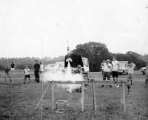
7UP lifts off on a very unsuccessful flight! |
Post-flight study
of the Seven-up revealed a number of possible sources of the observed
flight problems. First, it was recognized that the relatively large mass
of a massively-staged rocket would create a high potential for a low initial
flight velocity, particularly if care wasn’t taken to ensure high average
impulse motors were used for the lower stages. Any disruption of stability
early on would likely manifest itself in a fairly significant deviation
of the flight trajectory.
Accordingly, it seemed
possible that the separation of the stages had created an unbalance of
stability. This was likely caused by the aerodynamics of each finned stage
section separating. The force applied to the fins would cock the stage
as it separated, slightly binding in the coupler area, altering the fin
attitude, and changing the flight path of the rocket. Additionally, it
was theorized that slight centerline axial misalignment, caused by each
interstage coupling, may be multiplied over the length of such a “massively
multistaged” rocket. The resulting skewing of the centerline could result
in unpredictable flight trajectories. And in all cases of conventional
staging, the cumulative fin area of each stage created a strong weathercocking
tendency.
Francis
Graham's VICTORIA
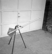
|
A possible solution was to build a multiple stage rocket with a non-separating
airframe, in which only the engines would blow out, stage-after-stage. Francis
Graham had earlier (1967) created a couple of massively staged rockets,
with solid, non-separating airframes, the Damsel Fly and the Victoria. These
vehicles used a stack of engines lined up in a metal tube, with the casings
being ejected under pressure from the higher stages. A herky-jerky thrust
like a multiple pump shotgun was thus obtained. Francis called this method
“dynamosequential staging.”
This kind of vehicle
was designed with the full knowledge of a couple of inherent design problems.
Such a rocket would need to be made of a fireproof material (aluminum
being used) as the upper stages would incinerate a conventional body tube.
More importantly, from the second motor upward, each motor would normally
suffer from the "Krushnik Effect", the thrust-cancellation phenomenon
that occurs when a motor thrusts inside an enclosed tube. But the Damsel
Fly and Victoria were intended to be “pulse-thrust” rockets, where after
the initial first stage boost, thrust would continue to be imparted in
pulses as a reaction to each subsequent stage as it was ejected from the
body tube. Also, short burn motors were used to minimize the buildup of
combustion gases in the tube between engine ejections, thus negating much
of the Krushnik effect. But, it can be imagined that this method did not
take best advantage of the thrust imparted by each engine stage, and long-burn
motors would create problems.
After the Seven-up
debacle, Ken Good was eager to give the problem of massive multi-staging
a shot. He liked the idea of a single piece rocket, and came up with the
concept of "open hull" construction. Accordingly (in November of 1969)
he built the KG-4 Achilles, a six-stage open hull single-body rocket.
It was a clear success, flying so well that it was not recovered; its
initial flight on February 1, 1970, saw it disappear into the gray clouds
over Tripoli Irwin’s “Launch Site A.”
 The
Achilles utilized four 3/16" wooden dowel rods to enclose the motors,
and yet leave them open to outside air to eliminate the Krushnik Effect.
It was this rack-like structure that had caused the term “rack-rocket”
to be coined. The rack contained a motor stack, the uppermost stage of
which was inserted into a conventional body tube that was joined to the
rack and contained the recovery system. As each motor ignited the next,
it was blown out between the dowel rods and clear of the rocket. Each
motor's stability, as it cleared the rocket, was guided by the dowel rods
so that no chance of unbalance could occur. Also, since the structure
was one unit and maintained a consistent alignment through all stages,
there was no chance of inter-stage misalignment to induce flight aberrations. The
Achilles utilized four 3/16" wooden dowel rods to enclose the motors,
and yet leave them open to outside air to eliminate the Krushnik Effect.
It was this rack-like structure that had caused the term “rack-rocket”
to be coined. The rack contained a motor stack, the uppermost stage of
which was inserted into a conventional body tube that was joined to the
rack and contained the recovery system. As each motor ignited the next,
it was blown out between the dowel rods and clear of the rocket. Each
motor's stability, as it cleared the rocket, was guided by the dowel rods
so that no chance of unbalance could occur. Also, since the structure
was one unit and maintained a consistent alignment through all stages,
there was no chance of inter-stage misalignment to induce flight aberrations.
 A.J.
Reed picked up in this concept, and developed it further. He built the
Learner, a three stage, open hull, single-body rocket as an attempt to
lighten the vehicle. It worked and was retrieved and used over. Several
others were built using various other techniques, cardboard and balsa
racks, instead of the bulky 1/4" dowels. The Learner and these other versions
disclosed some major flaws. The first was that the exhaust from the motors
would cause the wooden dowels to burn. This limited the rocket to only
a few flights before the rocket would have to be junked or the rack portion
would have to be completely rebuilt. The cardboard and balsa versions
burned immediately on first flight; the cardboard ones becoming unstable
in flight, and the balsa ones descending in flames! The quarter inch wooden
dowel versions proved best, but had excessive weight and were crude, both
in appearance and technology. A.J.
Reed picked up in this concept, and developed it further. He built the
Learner, a three stage, open hull, single-body rocket as an attempt to
lighten the vehicle. It worked and was retrieved and used over. Several
others were built using various other techniques, cardboard and balsa
racks, instead of the bulky 1/4" dowels. The Learner and these other versions
disclosed some major flaws. The first was that the exhaust from the motors
would cause the wooden dowels to burn. This limited the rocket to only
a few flights before the rocket would have to be junked or the rack portion
would have to be completely rebuilt. The cardboard and balsa versions
burned immediately on first flight; the cardboard ones becoming unstable
in flight, and the balsa ones descending in flames! The quarter inch wooden
dowel versions proved best, but had excessive weight and were crude, both
in appearance and technology.
A variation of this
was the self-disintegrating rack, developed by Francis Graham and tested
on the Drachenchen in 1982. Here, the racks were mated with long fins
which swept down starting from near the parachute compartment. The fins
and rack were allowed to simply burn away, thus saving on the weight of
fire-resistant materials and also ditching unneeded weight for the higher
stages. The disadvantage was that one didn’t get much of a rocket back,
merely a stub of its former self. Thus, there was little demand for this
design. Clearly, a better way was needed.
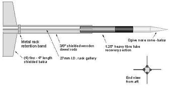 An
interim method to keep the rack and fin structure from progressive burn-effects
was revealed by Ken Good with his three-stage, KG-15 Exeter, first flown
in May 1981. The Exeter still used fiber- tubes, wood, and balsa for it’s
basic structure, but all areas that would be exposed to hot exhaust were
shielded with metallic automotive body tape. The result was a strong but
very lightweight structure, the Exeter’s empty weight being less than
½ pound. An
interim method to keep the rack and fin structure from progressive burn-effects
was revealed by Ken Good with his three-stage, KG-15 Exeter, first flown
in May 1981. The Exeter still used fiber- tubes, wood, and balsa for it’s
basic structure, but all areas that would be exposed to hot exhaust were
shielded with metallic automotive body tape. The result was a strong but
very lightweight structure, the Exeter’s empty weight being less than
½ pound.
 It
flew fantastically, and the heat shielding was effective. After it’s first
mile-high flight on two FSI F-100’s, and an F-7 third stage, the Exeter’s
basic structure was completely unaffected by heat; the rocket could therefore
be used again and again (the original Exeter still exists). This method
did require some stripping and re-taping of the rack area between flights
though, as the metallic tape did its job of taking the punishment of the
engine exhaust, and deteriorated to some degree as a result. It
flew fantastically, and the heat shielding was effective. After it’s first
mile-high flight on two FSI F-100’s, and an F-7 third stage, the Exeter’s
basic structure was completely unaffected by heat; the rocket could therefore
be used again and again (the original Exeter still exists). This method
did require some stripping and re-taping of the rack area between flights
though, as the metallic tape did its job of taking the punishment of the
engine exhaust, and deteriorated to some degree as a result.
One more rack rocket
effort would be tackled by Ken in the 1980's, the KG-16 Ajax of 1982.
This was in many ways a scaled down version of the Exeter, flying on a
stack of four C motors. It was very light, and minimum diameter, like
the Exeter. But Ajax's rack was constructed of small diameter aluminum
tubes, in place of the wooden dowel rods, in an effort to eliminate burn
effects without using the metallic tape. In the presence of Curt Hughes
and Ken, Ajax was launched in May 1982, in almost a sequel to the Achilles
flight. It flew extremely well, and disappeared into clouds (performance
was better than expected!) and was never seen again. The effectiveness
of the aluminum tubes could not therefore be ascertained in a post-flight
evaluation.
 Francis
Graham would seize on the Exeter concept for "Project Heliocom," Tripoli's
ambitious project to put a pellet into heliocentric orbit. Key to this
project (which cannot be fully described in this document) was a weather
balloon taking a launch complex into the high atmosphere, where upon balloon
bursting and a short free-fall of the launch complex, a multistage rack
rocket would be launched, looking much like the Exeter. This rocket would
ignite a shaped charge at the end of all stages firing; the shaped charge
would launch a pellet out of the atmosphere at escape velocity. It was
an intriguing project, which was never fully completed. Francis did build
a working model of the launch complex and rack rocket, both of which he
still possesses. This rack rocket project may yet see completion…. Francis
Graham would seize on the Exeter concept for "Project Heliocom," Tripoli's
ambitious project to put a pellet into heliocentric orbit. Key to this
project (which cannot be fully described in this document) was a weather
balloon taking a launch complex into the high atmosphere, where upon balloon
bursting and a short free-fall of the launch complex, a multistage rack
rocket would be launched, looking much like the Exeter. This rocket would
ignite a shaped charge at the end of all stages firing; the shaped charge
would launch a pellet out of the atmosphere at escape velocity. It was
an intriguing project, which was never fully completed. Francis did build
a working model of the launch complex and rack rocket, both of which he
still possesses. This rack rocket project may yet see completion….
An interesting “hand-off”
of the rack rocket concept took place at LDRS I, where Ken Good first
met Korey Kline and discussed the Exeter, which had been taken there but
was not flown. Korey liked the idea, and would later build some of his
own rack rockets, as would Tom Blazanin.

Korey Klines version
of the Rack Rocket follows Ken's design outline.
Tom’s and Korey’s
rack rocket work corresponded with advancements in model rocket technology
in the 1980’s, and they explored newer methods for rack rocket construction.
This included the use of the phenolic or fiberglass tubes, of the types
used in making composite motors. In the December 1985 issue of the Tripolitan,
Tom Blazanin published an article detailing his rack rocket efforts and
some of the then-current methods. This article is in fact an update of
that original 1985 piece.
Tom’s article described
in detail the construction of a new “Achilles” rack rocket. A portion
of the article is excerpted below. It can be seen that a fresh approach
was being explored.
“In a past issue of
the TRIPOLITAN we said we would cover the Chamai Leon, the new rack rocket,
in this issue. The Chamai Leon has been renamed the Achilles, after the
first cardboard rack rocket back in 1970.
"The Achilles
uses a piece of phenolic tube, 15" long and .99"i.d.,1.12"o.d. This accommodates
5 Estes D motors. Three slots are machined into the tube every 120 degrees.
These slots permit air to the motor exhaust, thus eliminating de-pressurization
and avoiding the Krushnic Effect. The entire rocket is simplicity at it's
best. The main airframe is a 14" piece of Crown 2212 motor tube, (or it's
equivalent). The nose cone is a Crown 4112, (or, again, it's equivalent).

Tom Blazanin's version
used machine slotted phenolic tube for the rack.
"The first step
is to machine the three slots in the motor rack section. This is not easy,
unless you have access to a milling machine. Once the slots are created
epoxy a thrust ring near the top end of the rack and then epoxy the rack
into the main airframe.
"The nose cone
is attached with a shock cord, the shock cord being attached in anyway
you are used to. Three fins must be epoxied to the phenolic rack every
120 degrees. The launch lugs can be standard 1/8", as used with the Achilles,
and installed in the normal locations with epoxy.
"The only thing
left is to prep the motors for use. The D motors will slide inside the
rack very loosely. We found this is not best. By gluing a 2" piece of
BT-50 to each motor, the motors become less sloppy within the rack, making
for more stable thrust, and still eject smoothly. Scotch tape the motors
together and wrap extra masking tape on the top motor to assure that it
will not be blown out at ejection.
"A rack rocket
makes an impressive launch to see, and hear. Liftoff is the same as any
model rocket, but staging is the thing! No deviation from the flight path,
whatsoever. Not at the first staging, nor the second, nor third, not even
the fifth! Just one STRAIGHT flight. Increasingly fast and very high.
We lost tracking and estimate 3000+ feet conservatively. The sound is
the next nice thing, especially to non-high power users. As the rocket
climbs higher we get that roar of ignition, like staggered ignition, except
it comes again, and again, and again! It really is different than standard
type staging.
"Deterioration,
caused by the exhaust heat and flame, to the phenolic tube is next to
none. The rocket can be used over and over again, far exceeding the ancient
wooden dowel version's life span.
"Test flights
and experimentation showed two important points. First is that the launch
angle must be 90 degrees from horizontal, straight up. The more the angel
is decreased from vertical, the greater the old ‘Pisa Effect’ will come
into play. A good straight vertical launch returns a great straight flight!
"The second point
is that successful Rack Rockets have been built and flown using 1/2" holes
drilled every 2.75", on the motor section, instead of the machined slots,
as shown in the pictures and drawing.
"Finally a way
is set for truly cheap altitude using model rocket motors. And it is so
much easier to do. The super stability demonstrated by the rack type rocket
leads to the next step in the project. Rack launched Astray-Cam!!…and
what about G motors!!!!!”
Tom had clearly learned
a number of valuable lessons that were incorporated not only into the
construction, but also into flight practice. One interesting point, which
Ken had very much in mind with the Exeter flights, is the value of mixing
motor types, using high average impulse lower stage motors to ensure adequate
initial velocities.
With the advent of
composite motors, a new problem for rack rockets emerged. None of the
new AP fuel motors were “directly stageable” in the manner that the old
black powder motors were. Tom and Korey experimented successfully with
modifying the delay grains to shorten or eliminate the delay, using the
ejection charge to ignite a piece of sleeved thermalite inserted into
the next engine to be ignited.
Interest in rack rockets
waned after some time, as all the rack rocket advocates moved onto to
other concepts or, in the case of A.J., left rocketry altogether. Ken
was inactive for some years, but upon becoming active again in 1996, the
rack rocket concept was revived. He designed a “B” version of the original
Exeter that would move the concept ahead logically.
While work and testing
for the new Exeter went slowly, another rack rocket design from the 1980's
was revived, in this case a complete redesign of a never-built rocket
from 1984, the KG-22 Bellerophon. Bellerophon was intended to use four
D motors to permit sport flying on limited size fields. It intentionally
was bigger in diameter than it needed to be, being designed around 24
mm motors, but with a rack structure mating to reinforced BT60 tubing.
Bellerophon's rack revived the aluminum tube method utilized by Ajax in
1982, but also had wooden dowels inside the tubes to resist bending.
The first flight test
of Bellerphon was not as successful as hoped. The wimpy D12 motors just
didn't give the initial boost needed and the rocket arced and flew horizontally
out of sight. Another was built, and an E30 motor used for stage one.
But the fused ignition method used failed, and stage 2 ignited, without
stage 1 ever firing - another horizontal flight and a crash at Sam Gordon's
launch in May 1998. Rebuilt, the Bellerophon was flown again in December
1998, using and E30 stage 1 and a version of the "modify the delay charge"
scheme to fire the upper stage D12's. In this form, the Bellerophon finally
flew well.
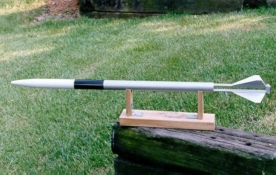
Completed BELLEROPHON with the aluminum motor rack. |
|

The motor cage, that would house the racked motors, shows the aluminum
frame. |

Ken pad-preps the BELLEROPHON |
|
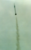
Successful liftoff into a perfect Rack Rocket flight. |
The new Exeter would
use aluminum tubing for the rack structure, with three longitudinal pairs
of 5/8" wide slots machined into the tubing. Originally, the entire hull
was to be made of aluminum, but this was deemed unessential, and instead,
the aluminum slotted tube rack would be joined to LOC 1.5 tubing. Aluminum
fins were used, and the entire rocket was made in a bolt-together modular
fashion, to facilitate repairs/replacements to any component and to permit
easier post-flight clean-up of the rack unit.

The KG15-B Exeter Awaits
launch day
Another intrinsic
design feature is that upper stage motors would be fired by onboard electronics,
in this case a Transolve T2T staging timer. The rocket was intended to
be flown on 29mm single use G-motors, with the final design spec indicating
that 7K feet was easily achievable. This design specification evolved
through 1997 and 1998, and included a number of static tests that looked
into versions of Tom and Korey's earlier direct staging methods. These
results were generally unsatisfactory, and it was felt that electronics
offered a much more reliable solution.
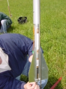
Ken attaches the igniter to the first motor within the rack. |
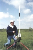
All is ready - as long as the gods agree! |

The long awaited liftoff and success of KG15B |
The Exeter project
proceeded in fits and starts, but was finally ready for flying in late
2000. Unfortunately, the weather at "Dragon's Fire 18" in October was
not cooperative, nor was it suitable at the first launch of 2001. Dragon's
Fire 20, on May 12, 2001 did not look promising either. But around mid-day,
the clouds broke, and in the presence of Tom Blazanin, Francis Graham,
and Ken Good, the KG-15B Exeter flew perfectly, all systems functioning
as designed.
For this flight, to
keep the apogee down in less than ideal conditions, Exeter flew with one
G80 and two E30's. Upon recovery, the slotted aluminum rack was undamaged,
requiring only post-flight cleaning for subsequent use. A more ambitious
flight, using all G-motors, may take place at LDRS- 20, July 2001.
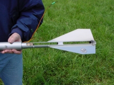
Post
flight view of the EXETER's slotted aluminum motor rack showing very little
damage or abuse.
|
As an odd footnote, while
researching some of the Exeter story, it was realized that on May 3, 1971,
Ken Good had announced at a Tripoli meeting his intention to build the first
three-stage F-engined Exeter. For many reasons, it took a decade to get
it done, but the first Exeter would fly ten years to the day (May 3, 1981)
from its announcement. The second Exeter would fly almost exactly twenty
years after the first. It is hoped that its successors won't take decades
to complete!
One may fairly ask
if the rack rocket concept still has currency. It is believed that it
does. Regardless of how large and powerful commercially available motors
may get, multiple staging will still be the preferred way to extend the
potential apogee of a rocket. Multi-staging also has the value of permitting
totally different motor profiles, corresponding to desired flight results,
to be blended into one flight. As long as multi-staging has value, so
will rack rocketry. New variations of the theme including motors that
parachute rather than just fall from the parent rocket, can be incorporated.
New materials, and new motor types hold forth interesting possibilites.
So where does the
rack rocket go from here? Apart from the efforts of others (Joe Pecklicz
built, flew, and lost, a four-stage D-motor rack rocket in 2000, and Paul
Bixler has announced intentions to build one), Ken has simulated upscaled
variants of the Exeter. Depending on what motors are used, anything from
12K to 40K+ apogees are possible. A three-stage K-250 powered rack-rocket
anyone?
There's another type
of "rack-rocket" under investigation. This one would be a strictly internal
rack structure, with motors being fed to the lowermost position rather
than firing in situ. Ken Good calls this an "internal engine delivery
rack" and Francis Graham and Richard Dietz, who subsequently discussed
the concept, call it "engine feed staging." Ken's ideas on how the engines
would be fed diverge from Francis and Richard somewhat. The concept will
be investigated further; the first such rocket, the KG-25 Drake is in
design form at present. It is hoped that the experience will be the basis
for a dream rocket, the two-stage Q-motor Terra Nova (originally designed
by Ken in 1997). But that too is a different story….
|


