The Space Shuttle has three major components: the orbiter, the solid
rocket boosters, and the external fuel tank. The external fuel tank is
the only piece of hardware that is not reused and burns up in the atmosphere
and falls into the ocean after it is jettisoned from the orbiter. The external
tank is made up of a liquid oxygen tank, a liquid hydrogen tank, and an
intertank. These components have been improved since the inception of the
Space Shuttle and now the materials are lighter weight and stronger. There
have also been ideas of placing the external tank into orbit and using
them as a space station for research, living quarters, and even entertainment.
The challenge of converting these external tanks has caused some problems
and this idea is still only perceived in theory.
The external fuel tank on the Space Shuttle is the
largest single integral part of the Shuttle system. According to Damon
(1995), “The external tank (ET) serves two purposes: it carries the propellants
for the orbiter’s three main rocket engines and it is the support structure
that connects the orbiter and solid rocket boosters (SRBs) together during
ascent to orbit” (p. 133). This paper will be an in-depth analysis of the
history and development of the components that make up the ET and also
the new structure that is being designed to decrease its weight. There
have also been ideas of placing the ET into an orbit and using them for
space or refueling stations. These issues and more will be discussed in
detail in the following report.
The concept of a reusable spacecraft is nearly
as old as that of flying machines itself. As the development of rocket
propulsion systems increased, the idea of entering space became a reality.
With this technology, the United States begun its research to construct
a vehicle that could be reused over and over again. On January 5, 1972,
President Nixon approved the three-element Space Shuttle consisting of
an Orbiter, rocket boosters, and a disposable propellant-tank (Gatland,
1981). This was the answer that has worked since the first test flight
on April 12, 1981 (Damon, 1995).
In 1975, the prime contractor for the ET was Martin Marietta
Aerospace. The first ET was assembled at the Michoud Assembly Facility
(MAF) in New Orleans, Louisiana in 1976. In July 1977, the fabrications
for the first flight ET began. The intertank structural test program was
completed in November 1977, and the first ET tanking test was conducted
in December 1977. After all the testing was completed, the first flight
ET (External Tank-1) was delivered to Kennedy Space Center in July 1979
(The External Tank, 1997).
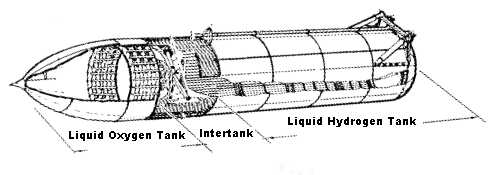
“The ET has three major components: the forward liquid oxygen tank, an unpressurized intertank that contains most of the electrical components, and the aft liquid hydrogen tank” (Dumoulin, 1988, p. 1). See Appendix A for picture of all the components. It is 154 feet long and 27.6 feet in diameter and carries more than 535,000 gallons of cryogenic propellants that are fed to the orbiter’s three main engines (LaNasa, 1997). “Prior to propellant loading, the ET weighs approximately 66,0000 pounds. But once liquid oxygen and liquid hydrogen are loaded into the vehicle beginning eight hours prior to Shuttle launch, the ET weighs 1.65 million pounds” (LaNasa, 1997, p. 1). The first five ET’s weighed approximately 77,000 pounds inert, which made it a heavyweight tank compared to the 66,000-pound lightweight tank.
The upper tank carries 1.36 million pounds of liquid oxygen at minus 297 degrees Fahrenheit (F) at liftoff (Damon, 1995). It is 331 inches in diameter, 592 inches long, and weighs 12,000 pounds empty with a volume of 19,563 cubic feet (143,000 gallons). See Appendix B for a picture of the liquid oxygen tank. Dumoulin (1988) describes its construction as follows:
“An intertank collar connects the two propellant tanks together and provides space for most of the electrical components” (Damon, 1995, p. 134). The intertank is 270 inches long, 331 inches in diameter, and weighs 12,100 pounds. See Appendix C for a picture of the intertank. Dumoulin (1988) better describes the configuration of the intertank as follows:
“The lower tank is about 2.5 times larger (383,000 gallons) and carries about a quarter of a million pounds of liquid hydrogen at minus 423 degrees F” (Damon, 1995, p. 133). It is 331 inches in diameter, 1,160 inches long, and 53,518 cubic feet of volume and weighs 29,000 pounds empty. The liquid hydrogen tank’s composition is specified below:
“The entire outer surface of the external tank is insulated with a half inch thick cork/epoxy layer covered with 1 to 2 inches of spray-on foam” (Damon, 1995, p. 134). “The system also includes the use of phenolic thermal insulators to preclude air liquefaction. Thermal isolators are required for liquid hydrogen tank attachments to preclude the liquefaction of air-exposed metallic attachments and to reduce heat flow into the liquid hydrogen. The thermal protection system weighs 4,823 pounds” (Dumoulin, 1988, p. 4) The two reasons protection is essential are because both propellants are very cold and they boil at very low temperatures. The following are problems that could happen if there was no insulation (Damon, 1995):
The external hardware, ET / orbiter attachment fittings,
umbilical fittings, electrical, and range
safety system weigh 9,100 pounds. Each propellant tank has a vent and
relief valve at its forward end. This dual-function valve can be opened
by ground support equipment for the vent function during prelaunch and
can open during flight when the ullage (empty space) pressure of the liquid
hydrogen tank reaches 38 psig or the ullage pressure of the liquid oxygen
tank reaches 25 psig. The liquid oxygen tank contains a separate, pyrotechnically
operated, propulsive tumble vent valve at its forward end. At separation,
the liquid oxygen tumble vent valve is opened, providing impulse to assist
in the separation maneuver and more positive control of the entry aerodynamics
of the ET. There are eight propellant-depletion sensors, four each for
fuel and oxidizer. The fuel-depletion sensors are located in the bottom
of the fuel tank. The oxidizer sensors are mounted in the orbiter liquid
oxygen feed line manifold downstream of the feed line disconnect. During
SSME thrusting, the orbiter general-purpose computers constantly compute
the instantaneous mass of the vehicle due to the usage of the propellants.
Normally, main engine cutoff is based on a predetermined velocity; however,
if any two of the fuel or oxidizer sensors sense a dry condition, the engines
will be shut down. The locations of the liquid oxygen sensors allow the
maximum amount of oxidizer to be consumed in the engines, while allowing
sufficient time to shut down the engines before the oxidizer pumps cavitate
(run dry). In addition, 1,100 pounds of liquid hydrogen are loaded over
and above that required by the 6-1 oxidizer / fuel engine mixture ratio.
This assures that MECO from the depletion sensors is fuel-rich; oxidizer-rich
engine shutdowns can cause burning and severe erosion of engine components.
Four pressure transducers located at the top of the liquid oxygen and liquid
hydrogen tanks monitor the ullage pressures. Each of the two aft external
tank umbilical plates mate with a corresponding plate on the orbiter. The
plates help maintain alignment among the umbilicals. Physical strength
at the umbilical plates is provided by bolting corresponding umbilical
plates together. When the orbiter GPCs command external tank separation,
the bolts are severed by pyrotechnic devices. The ET has five propellant
umbilical valves that interface with orbiter umbilicals: two for the liquid
oxygen tank and three for the liquid hydrogen tank. One of the liquid oxygen
tank umbilical valves is for liquid oxygen, the other for gaseous oxygen.
The liquid hydrogen tank umbilical has two valves for liquid and one for
gas. The intermediate-diameter liquid hydrogen umbilical is a recirculation
umbilical used only during the liquid hydrogen chill-down sequence during
prelaunch. The ET also has two electrical umbilicals that carry electrical
power from the orbiter to the tank and the two SRBs and provide information
from the SRBs and ET to the orbiter. A swing-arm-mounted cap to the fixed
service structure covers the oxygen tank vent on top of the ET during the
countdown and is retracted about two minutes before lift- off. The cap
siphons off oxygen vapor that threatens to form large ice on the ET, thus
protecting the orbiter's thermal protection system during launch (Dumoulin,
1988).
The range safety system provides for dispersing
tank propellants if necessary. It includes a battery power source, a receiver/decoder,
antennas, and ordnance. Various parameters are monitored and displayed
on the flight deck and control panel. These parameters are then transmitted
to the ground (Dumoulin, 1988).
The first weight reduction of 10,000 pounds in April 1983 resulted in increased payload. Now a new design will weigh another 7,500 pounds less. This lighter weight will allow the Space Shuttle to carry heavier cargo into orbit, which is a key element in building the international space station (Cabbage, 1995).
Parker Counts, manager of the External Tank Project at the Marshall Space Flight Center said, “The new external tank has passed one of the most innovative structural verification test programs ever designed, culminating with these proof tests” (Rahn & Malone, 1997, p. 1). The following is a description of the sate of the art test technology:
The following is a schedule of events that happen to the ET during a Space Shuttle launch. The time is displayed first, followed by the event (Damon, 1995):
There has been many ideas brought forward to use the ET as a space station or even a refueling station. “Martin Marietta has proposed modifying one tank to serve as a pressure vessel to house a gamma ray imaging telescope. Another possible use which has been proposed is as an orbital fuel storage facility to support on-orbit operations” (Bridwell, 1997, p. 2). “Some planners envision them clustered together as a space station, fitted with rockets and launched to the Moon for a lunar colony, or refitted a little at a time and used as orbiting gas stations for vehicles heading to the outer reaches of the Solar System” (Damon, 1995, p. 146). See Appendix D for a picture of the Space Station concept. The following is a simple idea for a space station:
The following is a portrayal from Tom Abbott, an ET enthusiast, of how an ET would be outfitted in orbit:
The technical challenges of placing an ET into orbit
include the circularization and maintenance of orbit, the cleanup and evacuation
of residual liquid oxygen and liquid hydrogen, and dealing with the foam
insulation (Fitch, 1997). There have been many different ideas of how to
solve these problems and they will be discussed further in the following
paragraphs.
The first problem is to get the ET in a circular
orbit and keep it there. “If left in a very low Earth orbit, the tanks
would have to be periodically boosted to higher altitude to keep them from
becoming a hazard to traffic and from eventually burning in. A costly alternative
is to strap on rockets and boot them to a higher stable parking orbit”
(Damon, 1995, p. 146). With that, some form of attitude jets would need
to be attached, plus a way to remotely control them. Tom Abbott said, “In
all on-orbit ET space station conversion proposals, a propulsion system
is installed just as soon as is practical and the ET remains attached to
the Space Shuttle until the is accomplished. Positive control of the ET
at all times is the only acceptable way to operate” (Fitch, 1997, p. 1).
When the Space Shuttle jettisons the ET, there are
from 5 to 20 tons of residual fuels remaining in the tank, and something
has to be done with them (Fitch, 1997). Tom Abbott said, “According to
a study undertaken at the direction of the ET Project Office, there are
three ways to accomplish this: (a) through the Orbiter’s fill and drain
valves, (b) through the Orbiter’s engines, and (c) through the ET vent
and relief valves. The first method is recommended. The second method has
the disadvantage that the vented hydrogen could affect the engine unfavorably,
and the third method requires modifications to the ET” (Fitch, 1997, p.
3).
There is concern that the Spray-On-Foam Insulation
(SOFI) could erode in orbit and cause annoying and potentially dangerous
debris (Fitch, 1997). Tom Abbott suggests his solution. “After the
ET reaches orbit, it can be held in a 170 mile high orbit while the SOFI
is scrapped off. One study predicts it would take less than a week to strip
the SOFI, and debris would deorbit in from hours to a couple of days, depending
on the size of the piece. Another is to leave the ET in a 160 mile orbit
for about a month and all the SOFI would oxidize off of it” (Fitch, 1997,
p. 4).
The ET is an important piece of equipment and without
it, the Space Shuttle would never make it into space. There have been many
improvements since the first ET was constructed, resulting in more payload
for the Shuttle to carry into space. These lighter weight designs have
even proved to be stronger and they provide more stability. As technology
expands, the reality of placing an ET into orbit and using them as a space
station could possibly happen. I feel this will happen in the near future,
basically because of the efforts by Gene Meyers and his Space Island Project.
It is best said by Bridwell (1997), “The ET is a proven, reliable piece
of hardware. The recently completed reassessment has only reinforced my
conviction that the tank will provide reliable service for many years to
come and will be the basis for many innovative adaptations” (p. 2).
Abbott, T. (1997). Outfitting an external tank in
orbit. [On-line]. Available: http://www.vswap.com/fitch/text/et_tom.htm
Ball, N., DeFilippo, R., Ritter, M., Skryd, K.,
and Ball, J. (1997). Space manufacturing and processing. [On-line]. Available:
http://cher.eda.doc.gov/oasc/spcmfg.html
Bridwell, P. (1997). External tank. [On-line]. Available:
http://spacelink.nasa.gov/NASA.Projects/….to.Flight/External.Tank-Porter.Bridwell
Cabbage, M. (1995, December 24). NASA working to
decrease weight of shuttle fuel tanks. Gannett news service, p. 1
Damon, T.D. (1995). Introduction to space. Malabar,
FL: Krieger Publishing Company
Dumoulin, J. (1988). External tank. [On-line]. Available:
http://www.ksc.nasa.gov/shuttle/technology/sts-newsref/et.html
Fitch, C.A. (1997). External tanks in orbit. [On-line].
Available: http://www.vswap.com/fitch/text/et_orb3.htm
Gatland, K. (1981). The illustrated encyclopedia
of space technology. New York, NY: Harmony Books
LaNasa, M. (1997). Space shuttle external tank.
[On-line]. Available: http://www.lmco.com/michoud/etfact1.html
NASA: Shuttle’s new lighter, stronger external tank
completes major pressure tests. [On-line]. Available: http://www.elibrary.com/getdoc.cgi?id=87…ydocid=522000@library_e&dtype=0~0&dinst=
Nead, A. (1997, November 12). First super lightweight
tank achieves major production milestone. [On-line]. Available: http://www.lmco.com/michoud/Slight.htm
Prado, M. (1997). Shuttles throwaway external tank.
[On-line]. Available: http://www.permanent.com/ext-tank.htm
Rahn, D. & Malone, J. (1997). Shuttle’s new
lighter, stronger external tank completes major pressure tests. [On-line].
Available: http://nexus.nasa.gov/Now/News/PAOArchive\97-058.html
The external tank. (1997). [On-line]. Available:
http://www.primenet.com/multimedia/space/rings.htm
Williams, N.P. (1997). Space shuttle super lightweight
tank. [On-line]. Available: http://www.lmco.com/michoud/slwtank.html
Source: (Damon, 1995)
Source: (Dumoulin, 1988)