The Assembly and Production of the External Tank
by
Dave R. Hunt
Abstract
The External Tank used on the Space Shuttle is assembled and produced
by Lockheed Martin at the Michoud Assembly Facility under direction of
the Marshall Space Flight Center. The production and assembly of the External
Tank is very extensive and precise and it must go through some vigorous
testing to ensure a flawless Space Shuttle launch. Since the External Tanks
inception, many changes have been made to reduce the weight and improve
the strength of the tank. A new Super Lightweight Tank has just been built
and will be used in the May, 1998 launch of Space Shuttle mission STS-91.
Now that the tank is stronger and lighter, many ideas have been brought
up to reuse this piece of space hardware, considering it now burns up in
the atmosphere and lands in a remote part of the Indian Ocean. Lockheed
Martin is involved in many new innovative programs and the idea of reusing
the External Tank must be taken seriously because this could open the door
to commercial industries in the development of space and technology.
Table of Contents
Abstract
Introduction
History of MAF
History of MSFC
History of ET Development and Testing
Components
Liquid Oxygen Tank
Intertank
Liquid Hydrogen Tank
MAF Production Capabilities
Super Lightweight Tank (SLWT)
Structural Verification Test
Other Products Made by Lockheed Martin
Future Uses
Conclusion
References
Appendix A – Picture of all Components
Appendix B – Picture of Liquid Oxygen Structure
Appendix C – Picture of Intertank Structure
Appendix D – Picture of Space Station
The Assembly and Production of the External Tank
Introduction
The External Tank (ET) used on the Space Shuttle
is assembled by Lockheed Martin Michoud Assembly Facility (MAF) under direction
from Marshall Space Flight Center (MSFC). The ET is assembled by combining
three major components: the forward liquid oxygen tank, an unpressurized
intertank that houses most of the electrical components, and the aft liquid
hydrogen tank. According to Damon (1995), “The ET serves two purposes:
it carries the propellants for the orbiter’s three main rocket engines
and it is the support structure that connects the orbiter and solid rocket
boosters together during ascent to orbit” (p. 133). This paper will cover
the history of the Lockheed Martin MAF and the MSFC, the components of
the ET, the assembly and production capabilities at MAF, the production
and testing of the new Super Lightweight Tank (SLWT), other products made
by the MAF, and future uses of the ET.
History of MAF
The MAF is located in New Orleans, Louisiana on 832
acres. It is 24 miles from the New Orleans International Airport and 15
miles from the sounds of Dixieland jazz in the French Quarter. LaNasa (1996)
describes why the plant was built and what it was originally used for:
In 1940, with the outbreak of World War Two, a 1,000 acre tract was
purchased by the U.S. government as the site of war-related construction.
Within three years, the world’s largest building at that time – 43 acres
under one roof – was completed, and plywood cargo planes and landing craft
rolled off the production line to aid the war effort. During the Korean
conflict the facility was again activated for the production of 12-cylinder
air-cooled engines for Sherman and Patton tanks. In 1961, with the space
race with the Russians heating up, the National Aeronautics and Space Administration
– NASA – took over the facility for design and assembly of large space
vehicles. The first space project at the Michoud facility was the design
and development of the first stage of the powerful Saturn booster, destined
to place man on the moon. Construction of the Saturn S1B and S1C boosters
continued at the Michoud facility until the early 1970s, when the Apollo
program wound down and work on the next generation launch vehicle, the
Space Shuttle, began (p. 1).
History of MSFC
“The Marshall Center is one of NASA’s largest centers,
occupying 1,800 acres in Huntsville, Alabama. Its primary mission is to
lead the Agency to develop and maintain space transportation and propulsion
systems and conduct microgravity research” (NASA, 1998, p.1).
Marshall was officially dedicated by President Dwight D. Eisenhower
on July 1, 1960, by the transfer to NASA of part of the Army Ballistic
Missile Agency. The center is named for former Secretary of State, Secretary
of Defense and Army World War II Chief of Staff, General of the Army George
C. Marshall. The center’s first director was Dr. Wernhervon Braun, the
noted German rocket scientist. In the past, Marshall has been identified
primarily as NASA’s launch vehicle development center. Today, this describes
but one facet of the center’s multi-faceted operation. Marshall is a multi-project
management, scientific and engineering research and development establishment,
with emphasis on projects involving investigation and application of space
technologies to the solution of problems on Earth as well as in space.
Marshall also plays a key role in many NASA mission operations. Marshall
had a significant role in the development of the Space Shuttle and continues
to manage the Space Shuttle main engines, the external tanks that carry
liquid oxygen and liquid hydrogen for those engines, and the solid rocket
boosters that, together with the engines, lift the Shuttle into orbit (NASA
SpaceLink, 1994, p. 1).
History of ET Development and Testing
It was on January 5, 1972, that President Nixon approved
the three-element Space Shuttle consisting of an Orbiter, rocket boosters,
and a disposable propellant-tank (Gatland, 1981). On September 1, 1973,
NASA announced that it had signed a contract with Martin Marietta Corporation
for the design, development, and test of the ET (NASA SpaceLink, 1998).
The first ET was assembled at the MAF in 1976. In July 1977, the fabrications
for the first flight ET began. The intertank structural test program was
completed in November 1977, and the first ET tanking test was conducted
in December 1977. After all the testing was completed, the first flight
ET (External Tank-1) was delivered to Kennedy Space Center in July 1979
(The External Tank, 1997).
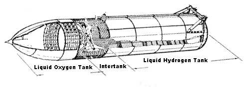
Components
“The ET has three major components: the forward liquid
oxygen tank, an unpressurized intertank that contains most of the electrical
components, and the aft liquid hydrogen tank” (Dumoulin, 1988, p. 1). See
Appendix A for picture of all the components. It is 154
feet long and 27.6 feet in diameter and carries more than 535,000 gallons
of cryogenic propellants that are fed to the orbiter’s three main engines
(LaNasa, 1997). “Prior to propellant loading, the ET weighs approximately
66,000 pounds. But once liquid oxygen and liquid hydrogen are loaded into
the vehicle beginning eight hours prior to Shuttle launch, the ET weighs
1.65 million pounds” (LaNasa, 1997, p. 1). The first five ET’s weighed
approximately 77,000 pounds inert, which was heavy compared to the 66,000-pound
lightweight tank.
The weight reduction was accomplished by eliminating portions of stringers
(structural stiffeners running the length of the hydrogen tank), using
fewer stiffener rings and by modifying major frames in the hydrogen tank.
Also, significant portions of the tank are milled differently to reduce
thickness, and the weight of the ET’s aft solid rocket booster attachments
were reduced by using a stronger, yet lighter and less expensive titanium
alloy. Earlier several hundred pounds were eliminated by deleting the anti-geyser
line. The line paralleled the oxygen feed line and provided a circulation
path for liquid oxygen to reduce accumulation of gaseous oxygen in the
feed line while the oxygen tank was being filled before launch. For each
pound of weight reduced from the ET, the cargo-carrying capability of the
space shuttle spacecraft is increased almost one pound (Dumoulin, 1988,
p. 1).
Liquid Oxygen Tank
The upper tank carries 1.36 million pounds of liquid
oxygen at minus 297 degrees Fahrenheit (F) at liftoff (Damon, 1995). It
is 331 inches in diameter, 592 inches long, and weighs 12,000 pounds empty
with a volume of 19,563 cubic feet (143,000 gallons). See Appendix
B for a picture of the liquid oxygen tank. Dumoulin (1988) describes
its construction as follows:
The liquid oxygen tank is an aluminum monocoque structure composed
of a fusion-welded assembly of preformed, chem-milled gores, panels, machined
fittings, and ring chords. It operates in a pressure range of 20 to 22
psig. The tank contains anti-slosh and anti-vortex provisions to minimize
liquid residuals and damp fluid motion. The tank feeds into a 17-inch-diameter
feed line that conveys the liquid oxygen through the intertank, then outside
the ET to the aft right-hand ET/orbiter disconnect umbilical. The 17-inch-diameter
feed lines permits liquid oxygen to flow at approximately 2,787 pounds
per second with the Space Shuttle Main Engines (SSMEs) operating at 104
percent or permits a maximum flow of 17, 592 gallons per minute. The liquid
oxygen tank’s double-wedge nose cone reduces drag and heating, contains
the vehicle’s ascent air data system (for nine tanks only) and serves as
a lighting rod (p. 2).
Intertank
“An intertank collar connects the two propellant
tanks together and provides space for most of the electrical components”
(Damon, 1995, p. 134). The intertank is 270 inches long, 331 inches in
diameter, and weighs 12,100 pounds. See Appendix C for
a picture of the intertank. Dumoulin (1988) better describes the configuration
of the intertank as follows:
The intertank is a steel/aluminum semimonocoque cylindrical structure
with flanges on each end for joining the liquid oxygen and liquid hydrogen
tanks. The intertank houses ET instrumentation components and provides
an umbilical plate that interfaces with the ground facility arm for purge
gas supply, hazardous gas detection, and hydrogen gas boiloff during ground
operations. It consists of mechanically joined skin, stringers, and machined
panels of aluminum alloy. The intertank is vented during flight. The intertank
contains the forward SRB-ET attach thrust beam and fittings that distribute
the SRB loads to the liquid oxygen and liquid hydrogen tanks (p. 3).
Liquid Hydrogen Tank
“The lower tank is about 2.5 times larger (383,000
gallons) and carries about a quarter of a million pounds of liquid hydrogen
at minus 423 degrees F” (Damon, 1995, p. 133). It is 331 inches in diameter,
1,160 inches long, and 53,518 cubic feet of volume and weighs 29,000 pounds
empty. The liquid hydrogen tank’s composition is specified below:
The liquid hydrogen tank is an aluminum semimonocoque structure of
fusion-welded barrel sections, five major ring frames, and forward and
aft ellipsoidal domes. Its operating pressure range is 32 to 34 psia. The
tank contains an anti-vortex baffle and siphon outlet to transmit the liquid
hydrogen from the tank through a 17-inch line to the aft umbilical. The
liquid hydrogen feed line flow rate is 465 pounds per second with the SSMEs
at 104 percent or a maximum flow of 47,365 gallons per minute. At the forward
end of the liquid hydrogen tank is the ET/orbiter forward attachment pod
strut, and its aft end are the two ET/orbiter aft attachment ball fittings
as well as the aft SRB-ET stabilizing strut attachments (Dumoulin, 1988,
p. 3).
MAF Production Capabilities
The following is an overview of what the MAF is capable
of producing and what tools are used throughout the facility (Ferrari,
1996):
The Michoud Assembly Facility is uniquely suited to large and
small manufacturing operations that require wide bays, up to 40-foot clear
height, access to production and material laboratories, and shipment by
water, rail or highway. Michoud contains over 3.7 million square
feet of manufacturing facilities, 700,000 square feet of office space,
200,000 square feet of laboratory space and a deep water port with convenient
access to the Gulf of Mexico. Fully automated, computer-controlled weld
equipment provides the most advanced welding for aluminum and aluminum-lithium
alloys. Michoud is the home of the world’s largest automated riveting machine
and weld lathes capable of manufacturing structures 28 feet in diameter.
The facility offers a wide assortment of machine tools such as knee mills,
CNC machining centers, hydraulic brake presses with 625 ton capacity, vertical
and horizontal boring mills. Michoud uses state of the art delivery systems
to apply thermal protection system materials to large space structures.
The environmentally controlled cells can apply epoxy primers, strippable
coatings and polyurethane foams to varying thicknesses. Michoud Space Systems
also is an industry leader in developing and using environmentally compatible
foams and blowing agents. The facility can conduct hydrostatic tests on
pressure vessels up to 28 feet in diameter and 94 feet long. One of the
largest automated facilities for interior and exterior cleaning of large
aerospace structures is also available. Wash and rinse process flow rates
are up to 900 gpm with temperatures to 120 degrees F. Engineering development
support capabilities include computer aided design and analysis. Use of
the latest CAD tools, such as parametric and solid modeling, finite element
modeling and dynamic manipulation permit the rapid development of design
concepts for new projects. Key technology laboratories conduct a broad
range of activities from chemical analysis, material and weld development,
metrology and a variety of NDE procedures. The chemical analysis lab is
capable of characterizing composites, metals and polymers, supporting contamination
control, failure analysis, engineering testing, routine material processing,
particulate identification and environmental analysis. The lab is equipped
with analytical instrumentation such as x-ray photoelectron spectroscopy,
scanning auger microscopes, secondary ion mass spectrometer and a scanning
electron microscope with energy and dispersice x-ray analysis capabilities.
The material and processes laboratory can evaluate a variety of materials
over a broad range of conditions, including fracture and mechanical testing
at temperatures ranging from –425 degrees to +2000 degrees F. Mechanical
tests can be designed for specific customer requirements such as ultimate
tensile yield strength, compression yield strength, shear strength, elongation
, fracture toughness and others. In the model shop/system development lab,
technicians provide hand-crafted master models, fabricate tools and test
specimens. Fabrication capabilities include a numerically controlled 50,000
psi water jet cutter and stereolithographic workstations to create precise
physical parts from CAD/CAM data. The weld development lab specializes
in the joining of aluminum, aluminum-lithium and other metal alloys with
a range of metal thicknesses from .09 to 1 inch thick. The lab utilizes
automatic variable polarity plasma arc and machine gas tungsten arc weld
capabilities. A 5-axis rectilinear gantry robot system allows welding of
unusual shapes and configurations in a variety of welding positions. The
lab also examines weld integrity with a variety of test methods such as
x-ray and dye penetrant. The structures lab offers complete end-to-end
capabilities. Computer controlled data acquisition systems are capable
of handling 500 channels of test instrumentation with acquisition rates
up to 250,000 samples per second. The lab also provides failure analysis
and reliability testing on propulsion components, vent valves and leakage
testing for pressurized seal joints (pp. 1-2).
Super Lightweight Tank (SLWT)
The first weight reduction of 10,000 pounds in April
1983 resulted in increased payload. Now a new design will weigh another
7,500 pounds less. This lighter weight will allow the Space Shuttle to
carry heavier cargo into orbit, which is a key element in building the
international space station (Cabbage, 1995).
Lockheed Martin Michoud Space System is assembling a super lightweight
version of the ET. By substituting Weldalite?, an aluminum-lithium alloy
developed by Lockheed Martin, and incorporating weight-saving design changes
and other efficiencies, the SLWT will weigh 7,500 pounds less than the
current design and thus improve Shuttle payload capacity by an equal amount.
Because the ET has almost reached orbital velocity with the orbiter at
main engine cut-off, every pound removed from the ET equals approximately
one pound of increased payload capability (Williams, 1997, p. 1).
The formulation for the aluminum-lithium, A1 2195, is one percent lithium,
four percent copper, 0.4 percent silver, 0.4 percent magnesium, with the
remainder being aluminum (Williams, 1997). “This alloy is weldable, 30
percent stronger and five percent less dense than the A1 2219 alloy previously
used in the ET. The new alloy also provides higher fracture toughness at
cryogenic temperatures, as low as minus 423 degrees F, versus room temperature
fracture toughness” (Williams, 1997, p. 1). Besides the new material, the
tank’s structure design has improved. “The walls of the redesigned hydrogen
tank are manufactured in an orthogonal waffle-like pattern, providing more
strength and stability than the previous design” (NASA, 1997, p. 1). “Manufactures
at NASA’s MAF will also try to keep the tank’s weight down with a new,
more precise way of applying the insulating foam coating to the exterior”
(Cabbage, 1995, p. 1). With the use of the new alloy, about 2.5 million
dollars will be added to the ET’s 50 million dollar cost now (Cabbage,
1995).
Structural Verification Test
Parker Counts, manager of the External Tank Project
at the Marshall Space Flight Center said, “The new external tank has passed
one of the most innovative structural verification test programs ever designed,
culminating with these proof tests” (Rahn & Malone, 1997, p. 1). The
following is a description of the state of the art test technology:
The proof test for the liquid oxygen tank was a hydrostatic, or water
pressure test. The tank was placed vertically on the test stand at NASA’s
Michoud Assembly Facility in New Orleans, LA, and filled with water, which
has similar density to liquid oxygen. The tests simulated conditions encountered
during flights and validated the design changes. The liquid hydrogen tank
was pressurized with gaseous nitrogen and subjected to conditions simulating
the thrust of the orbiter’s main engines and solid rocket boosters. Tests
checked the new design by exposing the tank to harsher conditions than
it will encounter in flight. After the tests, comprehensive X-ray and dye
penetrant inspections will be performed to further verify the tank’s flight
worthiness. The proof tests completed March 25 were the final in a series
of rigorous certification and structural verification tests (Rahn &
Malone, 1997, p. 1).
In October 1997, a notable production milestone happened when the mating
of the major components was completed. “The SLWT, designated ET-96, is
currently in Final Assembly at MAF for completion of mechanical, electrical,
and thermal protection system installations, and final acceptance tests.
The tank was delivered to NASA on January, 16 1998, in support of the May
1998 launch of Space Shuttle mission STS-91, the final scheduled Shuttle/Mir
docking mission concluding the joint U.S./Russian Phase 1 Program” (Nead,
1997, p.1).
Other Products Made by Lockheed Martin
“Lockheed Martin Michoud Space Systems designs and
assembles welded and composite
pressurized tanks for aerospace applications including the Space Shuttle
External Tank, the
X-33/VentureStar™ Reusable Launch Vehicle, the A2100 advanced communications
satellite and
the Kistler K-1 reusable launch vehicle” (X-33, 1997, p.1). The A2100
satellite will be capable of accommodating many different payloads to carry
out a wide variety of missions and is described as follows (Seal, 1996):
Lockheed Martin Michoud Space Systems is designing and assembling a
helium tank as part of the satellite’s pressure-fed rocket engine. Pressurized
helium from the tank will be used to maintain constant ullage pressures
in the engine’s fuel and oxidizer tanks as those liquids are expended.
The compact, lightweight tank is 32 inches long by 16 inches in diameter
and weighs 32 pounds. It is comprised of a thin (0.025 inch) titanium liner
and a graphite-epoxy composite overwrap one quarter of an inch thick. The
tank offers a significant weight savings over previous tanks, and represents
a high pressure tank technology currently unavailable elsewhere. A comparable
all-metal tank would weigh about 80 pounds. The tank will operate
under a normal pressure of 4,800 psi, with a minimum burst pressure of
7,200 psi (p. 1).
Also, the thermal protection material used on the ET is being made available
commercially for fire protection. “Today, Lockheed Martin insulating materials
are being used for aircraft engine nacelle protection and thrust reverser
fire protection, with a variety of other applications in review” (Baty,
1997, p. 1). Another technology Michoud Space Systems is studying is hybrid
propulsion.
The Hybrid Propulsion Demonstration Program (HPDP) consists of the
development and testing of 11-inch and 24-inch diameter hybrid motors,
for flight demonstrations by hybrid-powered sounding rockets completed
in spring, 1997, and development and static firing of several 250,000 foot-pound
thrust motors scheduled to begin in late 1997. Michoud Space Systems is
responsible for engineering and integration, feed and pressurization systems
analysis and design, heated helium pressurization and steam turbine drive
development, test operations and data analysis (Mitchell, 1997, p. 1).
Future Uses
The problem with the ET is that they are made for
a one-time use. This is good for Lockheed Martin because they will always
have to produce a new ET for all future Space Shuttle flights. There is
also an opportunity for Lockheed Martin to use these tanks after the Space
Shuttle gets into orbit. There have been many ideas brought forward to
use the ET as a space station or even a refueling station. “Martin Marietta
has proposed modifying one tank to serve as a pressure vessel to house
a gamma ray imaging telescope. Another possible use which has been proposed
is as an orbital fuel storage facility to support on-orbit operations”
(Bridwell, 1997, p. 2). “Some planners envision them clustered together
as a space station, fitted with rockets and launched to the Moon for a
lunar colony, or refitted a little at a time and used as orbiting gas stations
for vehicles heading to the outer reaches of the Solar System” (Damon,
1995, p. 146). See Appendix D for a picture of the Space
Station concept. The following is a simple idea for a space station:
Dozens of Station designs have been proposed, and the engineering for
each has been worked out is considerable detail. The simplest would be
to attach a habitable section at the base of the ET during the ET’s construction.
This Aft Cargo Carrier could be outfitted as living quarters for a half
dozen astronauts. It would be roughly the size of a 2-story house. The
crew would ride up in the shuttle, move to the habitable section once they’d
reached orbit and begin converting the ET upper 16 stories into laboratory,
production, and living areas. Once 2 or 3 of these single ET’s are in orbit
their crews could begin assembling additional ET’s into a ring, or other
design. A 12-ET ring would provide living quarters under one-quarter to
full gravity conditions. The ring would be one-third mile round with a
three deck interior holding living/working quarters and life support systems
for up to 400 people (The External Tank, 1997, pp. 1-2).
“This has been dubbed a wet launch of a habitat. It solves most of the
problems and expense of needing lots of robotic or human extravehicular
activity in space to outfit the tank with its desired contents. However,
since NASA has said that any use of the ET can’t have any effect on launch
performance, and this design has a more massive tank with a resultant loss
in payload capacity, it doesn’t look as if NASA will accept this. NASA
doesn’t like any redesign of the manned Shuttle system due to the potentially
lowering the safety to the crew by any mistakes due to redesign, e.g.,
structural dynamics” (Prado, 1997, pp. 3-4).
Even though NASA seems to be against the idea of
reusing the ET, many ideas of converting the ET’s safely have been conducted.
“Mark Holderman, a NASA engineer at the Johnson Space Center in Houston
has conceived of a Commercial/Industrial Process and Applications Platform
(CIPAP) called GEODE. The purpose of the GEODE project is to provide an
opportunity for the commercial and academic sectors to participate in space
activities while maximizing the potential for profit. He stated that GEODE
is not a research platform…GEODE is meant to be the vanguard space production
platform for commercial manufacturing work” (Ball, DeFilippo, Ritter, Skryd,
and Ball, 1997, p. 5).
Concurrently, the ET must be recognized as being an extremely valuable
article (piece) of precision space hardware which has as yet to be explored
for its on-orbit applications potential. The GEODE concept and its associated
design(s) are feasible, realistic, and evidence the embodiment of a very
cost effective approach to establishing a Commercial and Industrial presence
in Space. Developing a proactive environment that ardently promotes utilization
of new discoveries emerging from the unique and exclusive circumstance
of a GEODE type facility correlates well with the Western approach towards
capitalizing on technological advancements (Holderman, 1998, p. 3).
He believes it would take nine shuttle launches to complete the GEODE
project. “In its final form, GEODE would have a docking port, a crew module,
and a transport vehicle so that crew members could return to earth in the
event of an emergency” (Ball et al., 1997, p. 5).
Conclusion
The production and use of the ET are very important
to space exploration. Currently, the ET burns up in the atmosphere and
lands in a remote part of the Indian Ocean. Since the assembly, production,
and testing of the ET are so extensive, a new idea for reusing them shouldn’t
be overlooked. Lockheed Martin, MSFC, and NASA, along with commercial backing
could realistically use these ET’s for research in space. As a manager
for either one of these organizations, I would seriously consider what
advantage this idea would have compared to the other ideas to explore space
at a cost savings.
Holderman projected that the price tag on GEODE would be close to five
billion dollars, not including the cost of the nine shuttle launches it
would take to complete the project. He is confident, though, that the project
will actually end up costing half as much because of cost savings for minimized
launches, reduced logistics, and pay back due to the products being manufactured.
He believes that much of the return on the investment in GEODE will be
realized in the form of the profits generated from the emerging fields
of Nanotechnology and MEMS (Micro-Electro-Mechanical-System). Nanotechnology
sensors would enable significant medical advances, such as the constant
and unobtrusive monitoring of internal organs like the heart. The promise
of such emerging technologies causes Holderman to believe that the environment
of space may truly be the cradle for the next Industrial and Economic Revolution
(Ball et al, 1997, p. 5).
This all could be done without wasting the valuable resource we now throw
away, the ET. The technology to complete such a project is well within
our reach and by using what the experts know the ET could be a huge part
in learning what space has to offer us. It is best said by Bridwell (1997),
“The ET is a proven, reliable piece of hardware. The recently completed
reassessment has only reinforced my conviction that the tank will provide
reliable service for many years to come and will be the basis for many
innovative adaptations” (p. 2).
References
Ball, N., DeFilippo, R., Ritter, M., Skryd, K., and
Ball, J. (1997). Space manufacturing and processing. [On-line]. Available:
http://cher.eda.doc.gov/oasc/spcmfg.html
Baty, K. F. (1997, June 11). Thermal protection
materials, [On-line]. Available: http://www.lmco.com/michoud/thermal.htm
Bridwell, P. (1997). External tank. [On-line]. Available:
http://spacelink.nasa.gov/NASA.Projects/….to.Flight/External.Tank-Porter.Bridwell
Cabbage, M. (1995, December 24). NASA working to
decrease weight of shuttle fuel tanks. Gannett news service, p. 1
Damon, T.D. (1995). Introduction to space. Malabar,
FL: Krieger Publishing Company
Dumoulin, J. (1988). External tank. [On-line]. Available:
http://www.ksc.nasa.gov/shuttle/technology/sts-newsref/et.html
Ferrari, D. (1996, February). Michoud assembly facility
production capabilities, [On-line]. Available: http://www.lmco.com/michoud/facilit.html
Gatland, K. (1981). The illustrated encyclopedia
of space technology. New York, NY: Harmony Books
Holderman, M. L. (1998). GEODE: Commercial space
production facility, [On-line]. Available: http://www.spacefuture.com/archive/geode_commercial_space_production_facility.shtml
LaNasa, M. (1996, May 17). NASA michoud assembly
facility, [On-line]. Available: http://www.lmco.com/michoud/maf_site.html
LaNasa, M. (1997). Space shuttle external tank.
[On-line]. Available: http://www.lmco.com/michoud/etfact1.html
Mitchell, P. (1997, July 11). Hybrid propulsion
demonstration program, [On-line]. Available: http://www.lmco.com/michoud/hybrid.html
NASA/Marshall space flight center. (1998, March
9). [On-line]. Available: http://www.msfc.nasa.gov/paohome.gif.html
NASA: Shuttle’s new lighter, stronger external tank
completes major pressure tests. (1997, April 1). [On-line]. Available:
http://www.elibrary.com/getdoc.cgi?id=87…ydocid=522000@library_e&dtype=0~0&dinst=
NASA Spacelink. (1994, Sepetember 14). George C.
Marshall space flight center, [On-line]. Available: http://www.msfc.nasa.gov/omline/msfc/marshall.overview.html
NASA Spacelink. (1998, February 13). Early work
on the space shuttle, [On-line]. Available: http://www.msfc.nasa.gov/online/msfc/spacelink4.html
Nead, A. (1997, November 12). First super lightweight
tank achieves major production milestone. [On-line]. Available: http://www.lmco.com/michoud/Slight.htm
Prado, M. (1997). Shuttles throwaway external tank.
[On-line]. Available: http://www.permanent.com/ext-tank.htm
Rahn, D. & Malone, J. (1997). Shuttle’s new
lighter, stronger external tank completes major pressure tests. [On-line].
Available: http://nexus.nasa.gov/Now/News/PAOArchive\97-058.html
Seal, E. (1996, January 9), Helium tanks for the
A2100 satellite, [On-line]. Available: http://www.lmco.com/michoud/helium.html
The external tank. (1997). [On-line]. Available:
http://www.primenet.com/multimedia/space/rings.htm
Williams, N.P. (1997). Space shuttle super lightweight
tank. [On-line]. Available: http://www.lmco.com/michoud/slwtank.html
X-33 aluminum liquid oxygen tank successfully complets
proof test. (1997, November 17). [On-line]. Available: http://www.lmco.com/michoud/x33NR.htm
Appendix A
 Source: Damon, 1995)
Back to Components
Source: Damon, 1995)
Back to Components
Appendix B
 Source: (Dumoulin, 1988)
Back to Liquid Oxygen Tank
Source: (Dumoulin, 1988)
Back to Liquid Oxygen Tank
Appendix C
 Source: (Dumoulin, 1988)
Back to Intertank
Source: (Dumoulin, 1988)
Back to Intertank
Appendix D
 Source: (Ball et al, 1997)
Back to Future Uses
Source: (Ball et al, 1997)
Back to Future Uses
Back to the Table of Contents