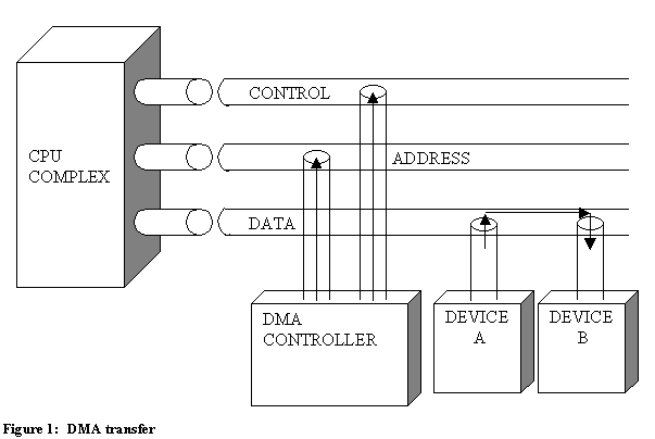


A DMA Controller is a device, which takes over the system bus to directly transfer information from one part of the system to another. This is necessary because often blocks of data have to be moved very rapidly, sometimes at speeds even faster than is practical, if each byte were to move through the CPU. For example, displaying pictures on a video screen requires a complete scan (one frame) of the screen 30 times a second or a half scan (one field) every 60 seconds. Suppose we wish to display a black and white picture that has 256 horizontal and 240 vertical dots, which are either on or off. Such a medium–resolution picture is usually scanned once every field and thus twice every frame. In this way each dot will actually appear as a double dot on the screen, and the whole picture will be scanned 60 times a second. Now 256 by 240 dots will require 61440 bits of information or 7680 bytes. Scanning through all of these 60 times a second means that there is a little over 2 microseconds to scan each byte. Each time the byte is scanned it has to be fetched from memory. This would be a complete waste of time for the processing power of the CPU.
For the computer to be efficient, it needs special circuitry to read these bytes. One solution is to store these bytes in a special display memory with built-in scanning circuitry and an arbitration scheme between the memory accesses by the scanning circuitry and memory accesses by the CPU. (This solution is mostly used today by the use of Video RAM – VRAM.) This is sometimes called a frame buffer. The memory in such a system is said to be dual ported because there are two different ways to access it.
In contrast, one of the first low-cost systems (the Cromemco Dazzler) stored these bytes in regular memory (single ported) and the scanning circuitry consisted mainly of a device called a DMA controller which actually took over the bus and generated it own address and controlled information on the system’s bus. The Dazzler actually had only about a third of the resolution in this example and it was designed to work with a clock speed of about 2 megahertz, but this presents a timing problem very comparable to the one in the example.
Because of the narrow or impossible timing constrains, DMA as described above is not recommended for direct scanning of regular memory for video display, but is the preferred method for making quick transfers of information. For example, DMA is often used when a picture or part of a picture needs to be moved quickly between a frame buffer and regular memory, or when the contents of buffers for a floppy disk need to be quickly transferred to new locations.
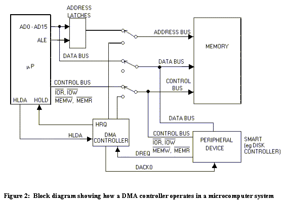
In general a DMA controller is used as follows: The DMA controller is told to make a transfer either by the CPU or some special circumstances; then the DMA controller makes a request to gain control of the bus from the CPU, other processors, or controllers which might currently be using bus; these other devices then relinquish control of the bus by putting their lines into tri-state condition (electrically disconnecting these lines); they then grant the bus to the DMA controller; and finally, the DMA controller takes over the bus, generating its own address and control signals for the bus and causing the transfer of information.

The Intel 82357 DMA Controller is used to perform DMA transfers. It comes with 40-pin package. The 82357 DMA Controller can provide service for a total of four different devices at once. For example, on 82357 DMA Controller might be handling transfers for two different CRT (Cathode Ray Tube) displays, a floppy-disk controller and a magnetic tape unit. Each device is assigned a channel in the 82357. By connecting several DMA chips together, any number of channels can be supported at once. The 82357 has registers to keep track of source and destination addresses, counts and masks, and commands and status. The 82357 is programmed by writing I/O bytes to special command and mode registers. Many options are available including timing, priority schemes, and location, size and type of transfer.
A special, compressed timing mode is available in which transfers are made in just two cycles.
Priority schemes are important. For example, if a DMA transfer is being made for a video display, then the DMA transfer should always take precedence over the CPU. Otherwise, blank spots will frequently appear on the screen.
You can make transfers whose source or destination is either a fixed I/O port or a block of memory. If the source or destination is in memory, then the address is automatically incremented (or decremented) after each access (byte move). If the source or destination is an I/O port, then the address should remain constant during the transfer.
The 82357 has a very useful feature called autoinitialization. When you select this, you automatically restore parameters (such as beginning address and count) for a channel after the transfer is completed. This way you can repeat the same action without needing to update the old counter parameters in the chip.
The Commonly used DMA Controller (Intel 82357)

The DMA circuitry incorporates the functionality of two 82C37 DMA controllers with seven independently programmable channels, (Channels 0-3 and Channels 5-7). DMA Channel 4 is used to cascade the two controllers together and will default to cascade mode in the Mode register. In addition to accepting requests from DMA slaves, the DMA also responds to requests that are initiated by software. Software may initiate a DMA service request by setting any DMA channel Request register bit to a 1.

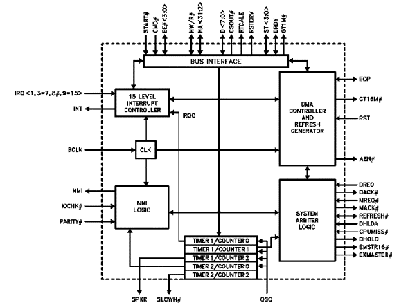
Figure 3: 82357 Internal Block Diagram
Any DMA channel may be programmed for 8-, 16 -, or 32-bit DMA device size and ISA compatible. Type A, Type B, or burst DMA Type C modes. The 82357 provide the timing controls and the 82558 EISA Bus Controller performs the data size translations necessary for the DMA transfer. The DMA memory addressing circuitry supports full 32-bit addresses for DMA devices. Each channel includes a 16-bit ISA compatible Current register which holds the 16 least-significant bits of the 32-bit address, a Low Page register which contains the eight second most significant bits, and a High Page register which contains the eight most significant bits of the 32-bit address.
2563FFh = 00000000 00100101 01100011 1111111 2
Example: How 2563FFh is found in the DMA channel
00000000r
High Page registe Most Significant Bits
00100101
Low Page register Second Most Significant Bits
01100011 11111111
Least Significant Bits
Current register
The channels can also be programmed for any of four transfer modes. The transfer modes include single, block, demand or cascade. Each of the three active transfer modes (single, block and demand) can perform three different types of transfer (read, write or verify). The DMA Controller also features refresh address generation, buffer chaining, auto-initialization, and support for a Ring Buffer Data Structure in memory. Stop registers are used to help support Data Communication or devices that work from a Ring Buffer in memory.
The DMA controller is at any time either in master mode or slave mode. In master mode, the DMA controller is either serving a DMA slave’s request for DMA cycles, generating refresh cycles, or allowing 16-bit ISA master to use the bus via a cascaded DREQ signal. In slave mode, the 82357 monitors the bus and decodes and responds to I/O read and write commands that addresses its registers.
When DMA is in mater mode and serving a DMA slave, it works in conjunction with the EISA bus controller (82358) to create bus cycles on the system bus. The DMA places addresses and the memory read/write (HW/R#) signal on the host CPU bus. It instructs the bus controller when to start and what type of bus cycle to run with the ST0 and ST1 lines. The bus controller informs the DMA when to place a new address on the bus with the DRDY signal.
References :
Microprocessors and Interfacing ~ Second Edition | |
The 8086 and 8088 Chipset | |
|
PC Guide |
![]()