When you talk about antennas, I would have to say, that the most important specification of an antenna, is its radiation efficiency. The ratio of power radiated to power fed to an antenna. Of course there are many types of antenna efficiency, For example how efficiently does the antenna radiate the power in the most desirable directions or the most desirable take off angles. Ninety percent of all communication that amateur radio operators do will require takeoff angles between 10 degrees and 60 degrees and the majority of time you are communicating between 20 degrees and 45 degrees.
So it makes no difference whether, you are talking to someone 50 miles away or 12,000 miles away these are the takeoff angles you'll need. When you use, a dipole, yagi, inverted V, vertical, or even a loop antenna that is parallel to the ground the range of takeoff angles you will have, is determined by the height of the antenna above ground, but when you look at how a vertically oriented horizontally polarized one wavelength loop antenna works you realize it is different the most obvious difference is it radiates at two different heights above ground.
This is very important, and highly desirable because the two different radiation patterns overlap each other thereby reinforcing and complementing each other this is because the loop in this configuration is actually two antennas in one the best way to visualize this is to look at the antenna as an inverted V dipole, at the top of the antenna and a V shaped dipole on the bottom. The center of the V shaped dipole is the feed point of the antenna. The inverted V dipole is double end fed from the ends of the V-shaped dipole that is beneath it. These two dipoles are operating as a phased array. They are electrically 180 degrees out of phase with each other.
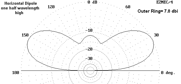
The distance between the two high current points is, four tenths of a wavelength, the first high current point is at the feed point and the second one is half way around from the feed point at the top of the antenna. The fact that they are electrically 180 degrees out of phase with each other and they are four tenths of a wavelength apart from each other is where the 3db gain of the antenna comes from. Who would have guessed that a single piece of wire could be so complicated. But as everyone knows a picture is worth a thousand words. Figure 1 below shows the elevation angle of a horizontal dipole at ½ wavelength above ground. Figure 2 shows the same antenna at one wavelength above the ground. Figure 3 shows the loop with the bottom of the antenna at ½ wavelength above ground and the top of the antenna at 9/10 of a wavelength above ground. As you can see from figure 3 the amplitude of your signal both on transmit and receive, does not change more than 2db from a 55 degree takeoff angle all the way down to 7 1/2 degrees so you can work short, medium, and long skip off of the Ionosphere simultaneously.
Figure 1

Figure 2
Figure 3
