|
Please Send Us Your
Comments and Suggestions At : dattarajrao@yahoo.com |
STEPS :
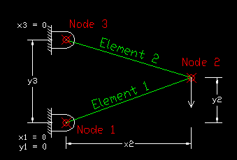
Enter The Coordinates Of
The Nodes And Properties Of The Connecting Elements. The
Figure Will Change According To The Data Entered.
The Elements May Be Drawn
Directly In Case Of Plane Truss Or The Connectivity Of
Nodes May Be Manually Entered.
Set The Displacement
Constraints. Example : x1 = 0 & y1 = 0.
Now Set The Forces Acting
On Various Nodes. Take care Of The Sign While Entering
Force In Each Direction.
The Program Will Obtain The Node Displacements, Stresses And Reactions Using FEM.