2nd gen RX-7 / Ford 2.3
2nd gen RX-7 / Ford 2.3
...2.3 Chassis Bracket Installation...
...12mm" wrench
...9/16" wrench
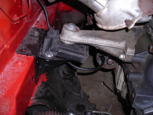
...The Chassis Brackets are marked on the underside, "R" for right, "L" for left. The hole next to the R or L mark is the hole that will line up with an existing threaded hole in the chassis. Place the bracket over that hole, and bolt it in place. Mark the remaining 8 "weld" holes in the brackets with a scribe or "sharpie", then remove the brackets.
...Remove the brackets, then use a grinder or wire brush to remove the paint on the chassis only in the areas marked where the rosette welds will be located.
...After removing the paint down to bare metal, paint the bare metal areas with weld-thru primer.
... Re-install the chassis brackets on the chassis.
NOTE: If you have a MIG welder, you can now fill in the weld holes in each bracket. If you do not have a mig welder, you can later have the exhaust guy do the welding for you.
...Loosely bolt the rubber engine side mounts into place on the chassis brackets.
...Remove the sway bar attaching brackets from the chassis and let the bar hang free.
Pre-Installation Cleaning / Detailing...
...This is probably your last chance to easily detail those places remote and
inaccessible, so take a quick look around before it’s too late.
Rigging Engine/Trans For Installation...
...For installation, the engine/trans should be rigged so that they naturally hang
level, or slightly tail down.
Dropping the Engine / Transmission into Position...
...Carefully lower the engine and transmission assembly into place. Line up and install the (2) 7/16x5" bolts that "pin" ihe mounts to the cradle.
Install the flat washers and de-formed thread loc-nuts. Torque these bolts/nuts to 10ft/lbs.
...After the engine/trans are in their approximate position, support the transmission,
with a floor jack or jackstand, with the output shaft centerline about 6-1/4” below the top
of the transmission tunnel.
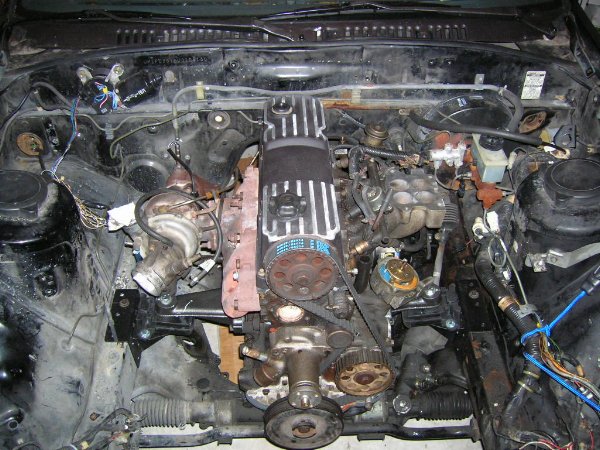
...Remove the engine hoist and chains.
When done, your install will look a lot like this...
...Transmission Crossmember Installation...
...14mm wrench
...14mm socket, rachet, and 6" extension
...3/8" allen socket
...9/16" wrench
...9/16" socket and torque wrench
AOD/C4/T-5 Crossmember Install...(RX-7s originally equipped w/ manual trans)
...this crossmember bolts directly to the existing RX-7 transmission crossmember holes,
using the original bolts.
Truss Style Transmission Crossmember Installation...(RX-7s originally equipped w/ automatic trans)
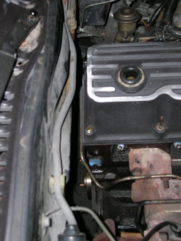
...Remove the shield that covers the fuel lines on the left side/bottom of the
floor pan, where they pass by the rear of the transmission.
...Install and loosely bolt the rubber transmission mount pad onto the transmission.
...Loosely bolt the crossmember onto the rubber trans mount pad.
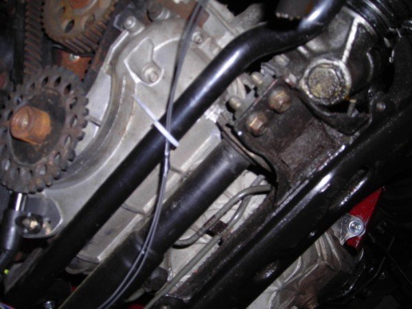
...Tighten all the installed trans mount and crossmember bolts. Properly positioned, the
crossmember spans the distance between the frame rails, leaving enough room for the fuel and
brake lines. Re-locating the fuel and brake lines is not required.
...Using a 3/8” drill bit, drill holes in the floor pan thru the (6) holes in the ends of
the trans crossmember (2 holes on each end).
...Install the supplied bolt plates from the top side of the floor pan, thru the new
drilled holes.
...From the bottom side of the floor pan, bolt the trans crossmember onto the bolt
plate studs, using the washers and nuts supplied. Tighten the bolts.
...Remove the floor jack (or jack stand) from under the transmission. The
engine/trans should now be resting on it’s own mounts, and supported by the chassis.
...Install sway bar spacers if required and re-attach sway bar.
...Checking Drivetrain Alignment / Clearances...
...The installed engine is centered in the car. The RX-7’s rear
differential’s pinion flange is offset 3/4” to the right of center. This is normal. The
engine/trans and the rear diff’s pinion centerline should be parallel, but NOT concentric.
If the centerlines were concentric (exactly lined up with each other), the u-joints would
fail prematurely as they need at least slight internal movement to lube properly.
While you are under the car, be sure to double check clearances at the...
....Steering rack / oil pan
....Harmonic balancer / oil pan / sway bar
....Hood / carburetor top etc.
Also check clearance between the oil pan and the steering rack & sway bar...
Driveshaft...
...The assembled driveline & slip yoke can be installed. The (4) pinion flange bolts should be
torqued to 27 ft/lb (Turbo II 43ft/lb). At least 3/8” of clearance should exist between all parts of the
driveline / transmission tunnel.
Although we sell new driveshafts for this application, an existing Ford driveline can be modified by a driveline shop to fit your converted RX-7. The proper way to get the correct length measurement is to insert the output yoke all the way into the transmission, then pull it out about 3/4 to 1”. This will insure that during normal in and out travel, the yoke will not bottom out during normal use. Measure from the center of the front of the u-joint to the flat face of the pinion flange on the rearend.
The ‘86-’91 model RX-7s use a driveline with very small non-replaceable u-joints. The NA and T-II driveshaft's rear pinion flange use the same pilot diameter, but Mazda used two different bolt patterns...
...NA rears (4) .393 dia holes on a 3.786” bolt circle
...Turbo II (4) .410 dia holes on a 4.120 bolt circle
When building a driveline for your RX-7, it is wise to use replaceable u-joints to keep future
replacement costs down. We have available a special rear driveshaft flange that uses a much
larger/stronger/replaceable u-joint, which bolts directly to your existing pinion flange .
All the driveshafts we sell include this special flange and large replaceable u-joints on both ends. No stock Mazda parts are used.
Shifter...
Automatic trans...It is possible to use the stock RX-7 automatic shifter to actuate the Ford C-4/AOD transmissions. Due to
the fact that the RX-7 shift lever is on the passenger side of the transmission and the Ford lever is on the
driver’s side, it is necessary to bend the part of the shifter that connects to the shift rod over to the
driver’s side. Fortunately, this is quite easy to do. It will then be necessary to fabricate a shift rod to
connect the shifter to the trans, also quite easy using hardware store rod stock.
...It is also quite easy to install a Ford floor mounted shifter from most any RWD passenger car.
T-5 Trans...Due to the location of the Ford engine, the T-5 shifter stub comes up about 3” ahead of the stock RX-7.
This dictates either a dog-leg shifter modification or a shifter relocation adapter to move the shift knob to
the origional RX-7 location. These methods are commonly used in Miata/Ford 5.0 conversions as well,
and are not nearly as drastic as the 6” rearward shifter offset used on the Cobra. Because these
modifications are under the shift boot, the origional look of the RX-7 interior is retained.
Clutch Linkage...
(manual trans only)It is possible to install a Ford style cable quadrant under the dash of your RX-7 and
retail the Ford cable linkage, but it is much easier to convert your cable actuated clutch to hydraulic
using a “push” style clutch slave using the origional RX-7 slave cylinder. This requires drilling 2 holes in the bellhousing, directly in back of the clutch fork opening, to position the slave to push the fork from the rear. It is also necessary to increase the size of the RX-7 clutch master cylinder to a 7/8" or 1” bore to get sufficient travel to release your Ford clutch (drift guys like the 1" for a quicker release).
...Connecting The Back-up Lite Switch...
...to operate the RX-7's back-up lites, Mazda used a transmission mounted SPST switch to complete the circuit.
When the RX-7's engine harness is removed with the rotary engine, part of this circuit is removed as well.
To restore this circuit, a harness extension will need to be added at connector X-04,
a rectangular 6 pole connector (2 rows of 3) located under the hood on the driver's side of the brake master cylinder.
2 of the wires in this connector are for the back-up lite switch. These wires wires are...
...black wire w/ yellow stripe- comes from 7.5a fuse in underdash fusebox.
...red wire w/ green stripe- goes to back-up lites.
Connecting these two wires together w/ a jumper wire will turn on the RX-7's back-up lites when the ignition switch is in the "ignition" and "start" positions.
Routing and connecting these two wires to your new transmission's back-up lite switch will enable the RX-7 back-up lites when "reverse" position of the shifter is selected.
2....Considerations & Requirements....
4....Engine / Transmission Installation....
5....Exhaust / Throttle Cable / Accessory Drive / Pulleys....
6....Cooling / Fuel Systems....
7....RX-7 Wiring Harness Connector ID and Circuit Locations....
8....Electrical System Modifications By Circuit....