This guide is for the LT1 PCM and harness that was installed in the '94-'96 Camaro and Firebird. It is easily identified from the earlier '92-'93 LT1 PCM and harness by the PCM connectors as follows...
'92-'93 LT1 uses 4 squarish PCM connectors, each with 22 pins total arranged in 4 rows. PCM connector A is grey, PCM connector B is red, PCM connector C is green, and PCM connector D is brown.
'94-'96 LT1 uses 4 long thin rectangular PCM commectors, each with 32 pins arranged in 2 rows of 16. PCM connector A is red, PCM connector B is black, PCM connector C is grey or clear, PCM connector D is blue. Be sure this is the type of PCM and harness you have before applying the info contained on this page.
In an attempt to make the necessary wiring modifications easier to understand, we have divided the information into 3 sections...
...'94-'96 LT1 Stock Harness & Connector Guide...
...Wiring Connections & Modifications...
...'86-'87 RX-7 Harness & Connector Guide...
The basic idea is to take LT1 connectors/terminals identified in the top section, apply the connection info in the middle section, and connect them to the RX-7 connectors/terminals identified in the bottom section.
The LT1 harness basically connects to the rest of the car thru a few specific connectors. The first two are located close together in the area of right shock tower...
...C100...black 10 pin connector.
............A- pink (injectors 2/3/5/8 ign/inj switched 12v 7.5amp power in)
............B- dk green w/ white stripe (AC comp relay control, PCM grounds to turn on AC)
............C- dk green (AC comp clutch status signal into PCM)
............E- brown (air pump relay control)
............F- brown (power in for fans)
............G- pink (switched 12v 15amp power in)
............H- dk blue (coolant fan relay control out)
............J- dk green (cooling fan 1 relay control out, PCM grounds to turn on a primary cooling fan)
............K- pink (injectors 1/4/6/7 ign/inj switched 12v 7.5amp power in) some harnessess
...C105...black 8 pin connector.
............B- pink (injectors 1/4/6/7 ign/inj switched 12v 7.5amp power in) some harnesses
............E- tan (serial data out)
The other three are located close together behind the firewall, inside the passenger compartment, on the other side of the firewall grommet.
...C210...
............?- purple (starter solenoid actuation power in from start switch)
............?- orange (12v 15amp fused constant power into PCM)
...C220...natural color 10 pin connector.
............A- red (alternator turn-on signal from instrument panel)
............B- tan (oil pressure gauge sender out)
............C- brown (oil level sender out)
............F- tan (serial data out)
............G- dk green w/ white stripe (VSS signal 4000ppm out)
............H- AUTOMATIC- dk blue (performance switch signal out to indicator lite)
................MANUAL- white (skip shift signal out to indicator lite)
............K- dk green (coolant temp sender out to gauge)
...C230...blue 10 pin connector.
............B- brown (signal out to SES lite)
............C- white w/ black stripe (diagnostic signal request input to PCM)
............D- white (tach signal out to dash)
............E- dark blue (VATS fuel enable input)
............F- dk green w/ white stripe (AC signal request)
............G- pink (12v 15amp fused ignition switched power feed into PCM, MAF)
............H- AUTOMATIC- lt blue w/ black stripe (TCC switched power in- wire thru a normally closed brake switch)
................MANUAL- brown (12v switched power in for reverse lites)
............J- AUTOMATIC- orange w/ black stripe (park/neutral switch signal in from switch)
................MANUAL- lt green (out to reverse lites)
There are two points that the LT1 harness needs connected are down by the LT1's starter...
...purple wire... needs to be connected to the starter solenoid's "S" terminal.
...open ground lug... needs to be connected to a block ground.
It is also necessary to put power to the LT1's ignition coil to get spark. There are 2 connectors on the coil, a grey one, and a black one. The black one has 2 terminals, A&B. Connect as follows...
...pink wire...on terminal "B" of black connector goes to a 12v 10amp fused ignition power source hot in "run & start".
The GM color code for wiring is very consistant. When in doubt, the following applies to any loose ends you might end up with in connectors C100, C101, C105, C220, and C230...
...red wires...all loose red wires should be connected to "12v+" protected by a fusible link.
...orange wires...all loose orange wires should be connected to "12v+" protected by a fuse of at least 10a.
...pink wires...all these wires in the LS1 harness should connect to a 12v "switched +" power source hot in "start" and "run".
...black...all these wires in the LT1 harness should connect to ground.
...black w/ white stripe...all these wires in the LT1 harness should connect to ground.
In the text below, the connector ID numbers are listed first are for '86-'87 harnesses. The 2nd ID numbers listed in brackets ( ) is the connector ID number for the '88-'91 harnesses. EXAMPLE- X-04(FE-02)...X-04 is the connector ID number for the '86-'87 harnesses, (FE-02) is the connector ID number for the '88-'91 harnesses.
The following set of connections take place mainly between the LT1's C100/C101/C102/C105 connectors and the Rx-7's X-16 connector, so much so that an 8 wire connecting harness could be made if one had the correct connectors to build it with. A little bit of caution is necessary with regards to the Turbo II models when dealing with the black w/ white stripe wires in the RX-7's X-16 connector, as the two that are side-by-side are "hot in run & start", and the one by itself near the missing center terminal is "hot in start only". The connections are as follows...
LT1 C100...
.........E- brown- connect to LT1 air pump relay coil's ground leg
...................(LT1 PCM grounds this leg to turn on it's electric air pump)
...................(required only for smog legal operation)
.........F- brown- connect to 12v 10amp fused ignition power source
...................(o2 sensor heating element and EGR vacuum control solenoid valve 12v 10amp fused power input)
.........pink- connect to RX-7 connector X-16's black w/ white stripe "hot in run & start" wire
.........pink- connect to RX-7 connector X-16's black w/ yellow stripe wire
LT1 C105...
.........pink- connect to RX-7 connector X-16's black w/ white stripe "hot in start & run" wire
.........white- (connection listed below in "tachometer signal wiring" section)
Re-connecting The Battery To The RX-7's Harness...when the rotary’s engine harness is removed from the car, a vital wire is lost that runs from the 80A fuse in the main fuse box to the large stud on the back of the RX-7’s alternator, and also to the ignition switch through connector X-23 (a large single terminal connector located between the main fuse block and the driver’s strut tower). This wire was originally black, and very thick, appx. 10ga. Be sure to replace it with wire of at least the same capacity, that connects all three points in the circuit, including the large stud on the back of the LT1 alternator.
Neutral Safety Switch...
...NA manual cars...LT1 equipped w/ 4L60E trans- Route a wire from RX-7's connector X-08(FE-05) black w/ white stripe "hot in start only" wire (next to the missing center terminal), thru the neutral safety switch, and back to RX-7's connector X-08(FE-05) black w/ red stripe wire. For LT1 equipped w/ T-56 manual trans- just connect the two terminals with a wire loop, as a neutral safety switch is not needed.
...NA automatic cars...If you are keeping your automatic car automatic, you need to route your purple wire in LT1 connector C210 thru a neutral safety switch.
...Turbo-II cars...On T-II cars, connector X-08 is a simple round 1 wire connector. If you kept a manual trans in your T-II, nothing needs to plug in here. If you installed an automatic in your T-II, you need to route your purple wire in LT1 connector C210 thru a neutral safety switch.
Locating & Re-wiring The RX-7's Fuel Pump Control Relay(s)...Mazda calls the main fuel pump relay the "Circuit Opening Relay", a square relay with a 6 terminal connector Ba-01(F-08) (2 rows of 3), which is located under the steering column. For the non-turbo models, this is the only fuel pump control relay. The Turbo II models used an additional relay called the "Fuel Pump Relay & Resistor", located in front of the passenger side strut tower under the stock air cleaner, using a round connector (F-09) with 6 terminals (2 rows of 3). The wiring modifications are as follows...
...ALL Models-...The RX-7 circuit opening relay's Ba-01 connector is a retangular 6 pin connector located below the RX-7's steering column. Perform the following modification steps 1, 2, and 3 to the wires/pins in the connector (step 4 is performed at RX-7 connector X-16/FEM-02/X-11)...
......STEP 1- remove the black w/ white stripe wire from the connector's center pin (opposite the blank hole). This wire will not be used, but it needs to be insulated from the others (as well as from the other wires) and taped back out of the way.
......STEP 2- remove the brown wire/pin from the connector and re-insert this wire into the upper center hole (spot formerly occupied by the black w/ white stripe wire we removed in step 1)
......STEP 3- remove the black wire/pin from the connector and re-insert this wire into the lower right spot to the left of the open hole (spot formerly occupied by the brown wire).
......STEP 4- connect the brown wire in the RX-7's X-16/FEM-02/X-11 connector to the LT1 C220 connector's terminal "B" dk green w/ white stripe wire.
These modifications allow the LT1's PCM to control the RX-7's Circuit Opening Relay as a fuel pump relay.
...Turbo II Only-...On the turbo models, there is also the "fuel pump relay and resistor". It's function was to provide extra fuel pressure under boost conditions by closing an internal set of contacts to effectively bypass a voltage dropping resistor. When installing a LT1, we bypass this entirely by connecting RX-7 connector Ba-01's blue wire w/ red stripe wire directly to the RX-7 connector X-13's blue wires (both blue wires are connected inside the harness - Mazda used 2 parallel blue wires thru the connector to reduce connection resistance). These blue wires power the RX-7's fuel pump.
Temp Sender Location & Installation...The RX-7's rotary engine's temperature sending unit for the dash gauge is a very small single terminal device located below the rotary engine's oil filter. It can be removed from the rotary and installed in your V-8' cylinder head (in between the front exhaust ports on driver's side) using a special reducing bushing. After installation, the sending unit should be connected to the LT1's temp sender wire in the harness (a dk green wire). Actual gauge connection is made by connecting the LT1 C220 connector's terminal K dk green wire to the RX-7's yellow w/ black stripe wire in connector X-16 (non-turbo) or X-15 (turbo II).
Oil Pressure Sending Unit Wiring... The rotary engine's oil pressure sending unit for the dash gauge is a large round single terminal device located below the rotary engine's oil filter. It can be removed from the rotary and installed into the top/rear of the LT1 block (just to the rear of the intake manifold) using a 1/8" pipe thread 45 degree elebow fittings (male threads for the block, female threads for the sender) to angle the sender away from the firewall. A single wrap of the threads with teflon tape should ensure leak free operation. After installation, the RX-7's sending unit should be connected to the LT1's original temp sender's tan wire. Actual connection of the oil pressure gauge to the dash is made by connecting the LT1 C220 connector's B terminal (tan wire) to the RX-7's X-04 connector's yellow w/ red stripe wire.
LT1/Delco Alternator Wiring...The '94-'98 LT1 alternator will require a low voltage input signal to trigger it's output. For proper operation, alternator terminal "L" needs to be connected to keyed "12v ign on" power source thru a 470 ohm resistor. The LT1 engine harness contains a red wire that connects the alternator's terminal "L" to connector LT1 C-220's terminal "A". Connect C-220 terminal "A" to the RX-7 harness as follows...
...Non-turbo models...Connect the LT1 C-220's terminal "A" red wire thru a 470 ohm resistor to the black w/ white stripe wire in the RX-7's X-15 connector.
...Turbo-II only...Connect the LT1 C-220's terminal "A" red wire thru a 470 ohm resistor to one of the black w/ yellow stripe wires in the RX-7's X-16 connector.
Tachometer Signal Wiring...The RX-7's tachometer originally got it's signal from the rotary engine's ECU. The stock rotary engine put out a tach signal that was the same rate as a 4 cyl piston engine. The LT1's PCM puts out a tach signal for a V-8. Simply using the LT1's tach signal to drive the RX-7 tach will result in a tach reading of twice speed. Re-calibration of the RX-7 tach is necessary. After re-calibration, connect the LT1 C230's terminal D white wire ("PCM tach signal output") to the RX-7's Ba-07 connector's yellow w/ blue stripe wire (formerly the signal input point for the RX-7's tach).
Back-up Lite Switch...To operate the RX-7's back-up lites, Mazda used a transmission mounted SPST switch to complete the circuit.
When the RX-7's engine harness is removed with the rotary engine, part of this circuit is removed as well.
To restore this circuit, a harness extension will need to be added at connector X-04(FE-02),
a rectangular 6 pole connector (2 rows of 3) located under the hood on the driver's side of the brake master cylinder.
2 of the wires in this connector are for the back-up lite switch. These wires are...
...black wire w/ yellow stripe- comes from 7.5a fuse in underdash fusebox. Connect this wire to the LT1 C230 connector's brown wire.
...red wire w/ green stripe- goes to back-up lites. Connect this wire to the LT1 C230 connector's lite green wire.
Low Coolant Level Warning Buzzer and Lite...the original sensor for this circuit was located in the RX-7's top radiator tank. If you do not want to go to the trouble to keep this part of the warning system intact, you can either dis-able the buzzer (located on the outside/bottom of the dash pod), or, simply locate the brown wire that formerly went to the coolant level sensor and connect it to ground. If you need help locating this wire, it is part of the front harness, a single wire leg that comes out of the front harness just in back of the passenger side headlite.
AC System- Relay, Compressor & Pressure Switch...Only 2 circuits need modification for your AC system to function properly.
...AC main relay (G-08)... in the #2 position in the relay rack located in the nose of the car just ahead of the hood latch. It has a square connector with 4 wires attached. It's terminals need to be re-connected as follows...
......blue w/ white stripe wire...connect this wire to one leg of the RX-7's pressure switch located near the RX-7's reciever/drier. The other leg of the pressure switch connects to "12v +" thru the "AC ON" switch.
......red w/ yellow stripe wire...connect this wire to ground.
......black w/ white stripe wire...connect this wire to the "+" side of your compressor's magnetic clutch. Connect the other leg of the magnetic clutch coil goes to ground.
......blue w/ black stripe wire...connect this wire to a "12v ign on" power source.
...AC pressure switch...a 2 terminal switch located next to the RX-7's reciever/drier. The switch's harness connector can be clipped from the front harness and re-used. The 2 legs of this switch/connector can re-wired as follows...
......blue wire...DO NOT CHANGE- oem wire connects to "12v +" thru the "AC ON" switch.
......blue w/ orange stripe wire...connect to the AC Relay's blue w/ black stripe terminal.
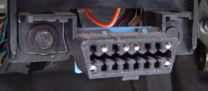 OBD Connector...this connector is not necessary to run your car, but it will likely be necessary to access the PCM's diagnostic features and will be required to pass a smog inspection. This 16 pin connector is arranged in 2 horizontal rows of eight, with the top row numbered left to right 1 thru 8, and the bottom row numbered 9 thru 16. The necessary connections are listed below...
...terminal 4- connect to ground
...terminal 5- connect to ground
...terminal 6- connect to LT1 connector C230's white w/ black stripe wire (field service enable)
...terminal 9- connect to LT1 connector C220's tan wire (serial data)
...terminal 16- connect to battery "12v+" constant power source.
Malfunction Indicator Lamp...this connector is not necessary to run your car, but will be required to pass a smog inspection. Most any 12v lamp will do, and many styles are available from any electronics supply store that can be easily installed in your RX-7. Connections to the "MIL" lamp are as follows...
...lamp leg 1- connect to a switched "12v+" ignition power source.
...lamp leg 2- connect to LT1 connector C-230's B terminal brown w/ white stripe wire.
The connector descriptions listed here are the '86-'87 style that are typically square or rectangular in shape. In '88, Mazda changed to a more weatherproof "round" shaped connector for it's harness-to-harness connections. The harness routing and wire colors are the same as the earlier '86-'87, it's just the connectors that changed. In '88 Mazda also changed the schematic style and connector ID numbers in their Factory Wiring Diagram Manuals. The '86-'87 and '88-'91 factory schematics appear very different, but it's just that they are drawn using a different layout style. Although the different style connectors are incompatible, the wire routing and color codes are nearly identical. In the information below, we will list the connector ID numbers for the '88-'91 RX-7 in ( ).
The RX-7 has 3 main harnesses located in the engine compartment area...
Front Harness... this harness is the main harness for the front of the RX-7. It's basic job is to connect all the other sub harnesses
in the front to the rest of the car. It comes thru the firewall on the extreme driver's side of the firewall, and runs forward to the
radiator support to the relay rack (under the plastic cover in front of the radiator), and across to the horns, the coolant level sensor
(in the top of the RX-7 radiator), headlites, front parking lites, etc. The front harness also connected to the engine harness at X-04, X-05, X-06, and X-08.
It connects to the Emissions harness at X-15, and X-16. It connects to the instrument panel harness at X-10 and X-11.
Engine Harness... this harness is located on the driver's side of the engine compartment. It contains wires
to the rotary engine's battery cables, ignition system, starter, alternator (non-turbo), oil pressure sender, transmission switches, dash gauges, and various warning sensors. This harness is no longer needed, but it contains
some connectors which should be salvaged for later use.
Emissions Harness... this harness is located on the passenger side of the engine compartment. It contains wires between the rotary
engine's ECU to the rotary's injectors and ECU sensors. Most of this harness is no longer needed, but it also
contains wires to the wipers, cruise control, water temp sender, and alternator (turbo only), which should be retained when the rest of the
harness is removed.
Connector X-01...is located on the side of the main fuse box, located just ahead of the driver’s side strut
tower.
...Black...when the rotary’s engine harness is removed from the car, a vital wire is lost that runs from
the 80A fuse in the main fuse box to the large stud on the back of the RX-7’s alternator, and also to the
ignition switch through connector X-23 (a large single terminal connector located between the main fuse
block and the driver’s strut tower). This wire was originally black, and very thick, appx. 10ga. Be sure to
replace it with wire of at least the same capacity, that connects all three points in the circuit.
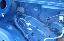
Connector X-04 (FE-02)... the RX-7's Engine harness connects to the Front harness at X-04 (FE-02), a rectangular plug with 6 conductors
(2 rows of 3), located between the left front strut tower and the firewall. Listed below are the wires of
interest that can be accessed at this connection:
...Black w/ white stripe... there are 2 of these wires, which are 12v+ when the ignition is on.
...Yellow w/ red stripe... this wire goes to the RX-7's engine's oil pressure gauge.
...Black w/ yellow stripe... this wire is the power wire to the RX-7's back-up lites.
...Red w/ green stripe... this wire goes back to the back-up lites.
Connector X-05 (FE-03)... the RX-7's Engine harness connects to the Front harness at X-05 (FE-03), a rectangular plug with 6 conductors (2 rows of 3) located between the left front strut tower and the firewall. Listed below are the wires of
interest that can be accessed at this connection:
...Black w/ white stripe... TURBO-II ONLY- this wire went to the Turbo II RX-7's alternator connector A-02 (E-02), and gets 12v "+" thru a 15a fuse when the ign switch is in the "start" and "run" positions.
Connector X-08 (FE-05)...Description of this connector changes depending on if the car was NA or T-II (NOTE- if you are salvaging X-08 from the engine harness, note that some wire colors change in this half, and the manual trans NA cars will have 2 black w/ white stripe wires).
NA cars...this connector is a 6 conductor (2 rows of 3) located between the firewall and the left strut tower.
...black w/ white stripe...this wire is "hot in start only" power to the neutral safety switch.
...black w/ red stripe wire... this wire goes out to starter's "S" terminal thru X-16
Turbo II cars...this connector is a simple round 1 terminal connector with a single black w/ white stripe wire that needs no connection (we took care of the starter "S" connection in X-16)
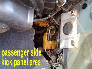 Connector X-15 (FEM-01)... this is a rectangular 15 pin connector (2 rows, 1 of 8, 1 of 7) between the front harness and emissions harness, located in the RX-7's passenger kick panel area.
Wires of interest are:
Connector X-15 (FEM-01)... this is a rectangular 15 pin connector (2 rows, 1 of 8, 1 of 7) between the front harness and emissions harness, located in the RX-7's passenger kick panel area.
Wires of interest are:
...Black w/ white stripe... (non-turbo only) 12v "ign on" wire that went to RX-7's alternator.
...Yellow w/ black stripe... (turbo only) this wire goes to the RX-7's coolant temp gauge.
...Blue... this wire provides power to the wiper motor thru a 15 amp fuse at X-07 when the ignition switch is in the "RUN" position. It needs to connect to the plug at the wiper motor if the emissions
harness is completely removed.
...Blue w/ yellow stripe... this wire needs to connect to the plug at the wiper motor if the emissions harness is completely removed.
...Blue w/ white stripe... this wire needs to connect to the plug at the wiper motor if the emissions harness is completely removed.
...Blue w/ red stripe... this wire needs to connect to the plug at the wiper motor if the emissions harness is completely removed.
...Black... this wire needs to connect to the plug at the wiper motor if the emissions harness is completely removed. It grounds the wiper motor case.
...Green... this wire needs to connect to the plug on the cruise control actuator if the emissions harness is completely removed.
...Green w/ black stripe... (across from green wire) this wire needs to connect to the plug on the cruise control actuator if the emissions harness is completely removed.
...Green w/ white stripe... this wire needs to connect to the plug on the cruise control actuator if the emissions harness is completely removed.
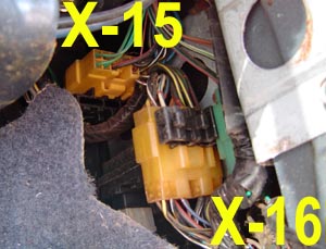 Connector X-16 (FEM-02)... this is a rectangular 13 pin connector (2 rows, 1 of 6, 1 of 7) between the front harness and emissions harness, located in the RX-7's passenger kick panel area.
Wires of interest are:
Connector X-16 (FEM-02)... this is a rectangular 13 pin connector (2 rows, 1 of 6, 1 of 7) between the front harness and emissions harness, located in the RX-7's passenger kick panel area.
Wires of interest are:
...Black w/ yellow stripe... these 2 wires are switched by the main relay thru a 40amp main fuse. The ignition switch energizes the relay in the "RUN" position, making it a good source for injector power.
...Black w/ white stripe... these 2 wires are switched by the normally closed side of the starter cut relay, energized from the "START" side of the ignition switch (powered by 80A main fuse). They are also powered by the normally open side of the main relay, which energizes them when the ignition switch is in the "RUN" position thru a 30amp main fuse. They formerly powered most of the rotary engine's emissions and control solenoids and switches.
...Brown... this wire comes from the circuit opening relay's Ba-01 connector and needs to be connected to the LT1 harness's C-220 connector terminal "B" green w/ white stripe wire to enable the LT1's PCM to control the RX-7's fuel pump.
...Blue w/ red stripe... this wire comes directly from the "+" side of the battery thru a 7.5 amp fuse at X-07 (which gets it's power from a 60 amp main fuse).
...Yellow w/ black stripe... (non turbo only) this wire needs to be connected to the rotary engine's water temp sending unit (installed in the Chevy engine) for the RX-7 dash gauge to work.
Connector Ba-07 (F-35)... the tach signal wire is most easily accessed at the Ba-07 connector that went to the RX-7's trailing coil,
located just in front of the left strut tower:
...Yellow w/ blue stripe... this wire is the tach signal wire.
Connector Ba-01 (F-08)... the 2nd gen RX-7s use a circuit opening relay to allow the rotary engine's ECU to control the fuel pump.
The relay is located under the dash above the steering column, and has 5 wires in a 6 place connector (2 rows of
3), identified as follows:
...Black w/ white stripe...(1 in NA cars, 2 in turbo only)
...Black w/ red stripe...(turbo only)
...Brown...
...blue (NA) or blue w/ red stripe (turbo only)...
...black...
Connector G-06... this 2 connector plug onto the refrigerant pressure switch (located on the right side under the plastic
panel in front of the hood latch), in the line between the drier and condenser. Points of interest are:
...Blue... this wire comes from the AC thermostat.
...Blue w/ orange stripe... this wire needs to be connected to a 12v+ ignition power source in order to
power the fan amplifier.
Connector G-08... this connector plugs into the AC main relay, located under a plastic panel in front of the hood latch.
Wires of interest here are:
...Blue w/ black stripe... this wire is power from the ACC side of the ign switch, fused at 10A.
...Red w/ yellow stripe... is from the blower control unit.
...Black w/ white stripe... this wire goes to the AC compressor clutch magnet.
...Blue w/ white stripe... this terminal/wire needs to be grounded to allow the AC clutch to be
energized. It was formerly grounded by the RX-7's ECU.
The engine harness is removed with the rotary engine, but a few of it's connectors should be salvaged to make connecting to the front harness easier. Those connectors are...
Connector X-04 (FE-02)... the RX-7's Engine harness connects to the Front harness at X-04 (FE-02), a rectangular plug with 6 conductors (2 rows of 3), located between the left front strut tower and the firewall. Save this connector and a short section of wire to make connections at the Front Harness's side of X-04.
 The RX-7's emissions harness provided the main connection between the rotary engine's ECU , it's sensors, and it's fuel injectors. The emissions harness passes thru the RX-7's firewall on the passenger (right) side. It can be removed entirely, except for the wires listed below. The RX-7 ECU, located on the other side of the firewall (on the right side under the passenger floorboard), is no longer needed either. All the wires from the ECU to the RX-7
engine and sensors, located mainly on the right side of the engine bay, can be removed. The wiper
wiring runs in the same harness, so split the loom and save the following wires:
The RX-7's emissions harness provided the main connection between the rotary engine's ECU , it's sensors, and it's fuel injectors. The emissions harness passes thru the RX-7's firewall on the passenger (right) side. It can be removed entirely, except for the wires listed below. The RX-7 ECU, located on the other side of the firewall (on the right side under the passenger floorboard), is no longer needed either. All the wires from the ECU to the RX-7
engine and sensors, located mainly on the right side of the engine bay, can be removed. The wiper
wiring runs in the same harness, so split the loom and save the following wires:
Alternator wires (non-turbo models only)...
...Black w/ white stripe... comes from ign switch "on" 12v (can also be found in X-15), connects to the upper horizontal of the RX-7 alternator plug's "T".
...White w/ black stripe... comes from alt warning lite relay (can also be found in X-15), connects to the lower vertical leg of the RX-7 alternator plug's "T"
Wiper wires...
...Blue...a power wire directly to the wiper motor from the ignition switch's "ignition" position.
...Blue w/ yellow stripe...to the wiper motor from the delay relay.
...Blue w/ white stripe...connected between the switch and wiper motor.
...Blue w/ red stripe...connected between the switch's "hi" position and wiper motor.
...Black...wiper motor ground.
Water temp sender wire...
...Yellow w/ white stripe...
Cruise control wires......
...Green...power wire to coil of actuator's relay. Also powers "cruise" lite in the dash.
...Green w/ black stripe...
...Green w/ white stripe...
...Green w/ yellow stripe...
The Emissions harness can be removed after the above wires are salvaged, but a few of it's connectors should be salvaged to make connecting to the front harness easier. Those connectors are...
X-15...
X-16...
The description and location of these connectors is listed in the front harness section above.