
Special Parts Required To Duplicate Our 4 Rotor...
The coupling design...
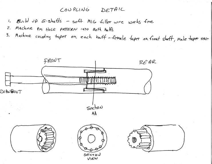
Here are some basic descriptions of the key parts needed to build your own 4 rotor. We will start with the coupling design.
The basic geometry is that of a tapered/pinned coupling, with a male and female component. The male half is machined into the front of the rear e-shaft, and the female half is machined into the rear of the front e-shaft. The total length of the mating tapers is exactly 1.000". The major diameter of the taper is 1.400", and the minor diameter is 1.200". Angle of the taper is 5 degrees, 43 minutes.
Arranged about the parting line of the taper is (12) 3/16" aluminum pins, evenly spaced on a 1.300" pin circle diameter. These pin holes are bored parallel to the e-shaft centerline. Total length of each of the (12) pins is 1.500", with .250" of each end of the pins rooted in the front and rear e-shafts. A 3/8" dia. draw-bolt passes completely thru the center of the front e-shaft, anchored in the internally threaded male component of the rear e-shaft. Ours was conviently made from a section of 3/8x24 fine thread B-12 redi-rod. A nut over a hardened washer in the center of the front pulley was torqued to 35 ft/lbs to draw the two e-shafts together. A bit of sealer is a must to prvent oil leaks.
The pin hole drilling jig...
We made a drilling jig to locate the (12) pin holes for boring. This ensured that both halfs of the coupling had exactly the same pattern, and allowed rotation of the pin pattern prior to drilling to adjust the indexing of the shafts. The jig was made of solid steel, with the center bored out to the same diameter as the main bearing journal, so that the jig could be placed over the end of the shaft for a full 2". (3) radial set screws were arranged 120 degrees apart to allow precision adjustment of the pattern for eliminating run-out. The open end of the jig was slit in (3) places, each 120 degrees apart, and 3 more screws were used to close the slits to secure the jig to the shaft.
The front eccentric shaft...
The rear section beyond the rear main bearing area must have material added so that the front half of the coupling can be machined into it. We mounted the shaft in a lathe, and added the material using a MIG welder w/ standard steel wire. Add enough material to the former flywheel mounting section to maintain the full 1.690" diameter of the rear main bearing journal for a total length of 3.050" from the face of the rear rotor journal. After everything slowly cools off, the added material can be machined to the same dia. as the main journal, and faced off at 3.050" total length (from the rear rotor journal). Do not machine the internal taper for the coupling female section yet, until after the (12)pin holes are bored. After drilling the (12) pin holes to a total of 1.255, the female taper of the coupling can be machined out of the inside of the shaft. The length and major/minor diameters are listed above.
The center of the shaft must be bored out to allow room for oil to flow around the draw-bolt that must pass thru the center of thr front e-shaft to draw the coupling together. We drilled the center of the front e-shaft out to about 9/16", using a drill bit that was modified by welding a long extension to the shank.
The rear eccentric shaft...
The front section of the rear e-shaft is built-up using the same method as used for the front e-shaft, except that it is built up to the full 1.690" diameter of the main bearing journal for a total distance of 3.690" from the front face of the #3 rotor journal. This dimension includes the 1.000" long male component of the coupling taper, which is not machined to it's finished diameter until after the (12) pin holes are bored. Use the same method to locate and drill the pin holes as was used for the front e-shaft, except pay close attention to the positioning of the holes as they are used to index the phasing of the shafts. After the (12) pin holes are bored to a total depth of 1.255" ea, the male taper can be machined into the front of the rear shaft. The center of the male taper is drilled and tapped to 3/8"x24 internal thread, required for anchoring the draw-bolt
The pilot ring...
The pilot ring is machined from a 4.750" dia. x 1.150 long solid blank of solid steel. Although aluminum may work, we felt that since this ring pilots the 2 engines main bearing bores in proper alignment, the extra weight was an acceptable trade-off.
Here's a crude sketch of the pilot ring (from my old shop notes) for my friend in So. Africa.....

The 3.740 dia. side of the pilot ring fits into the area of the rear stationary gear formerly occupied by the E-shaft's rear main seal, in the front engine.
The 2.365 dia. side of the pilot ring fits inside a recess in the front stationary gear of the rear engine.
I'm still trying to remember what the 3.125 ID represents in the lower portion of the drawing.
The mid-plate...
The oil pump drive sproket...
Water pump / cooling...