
THE EAST WHARF (a subjective view)
A. Selection of Scheme
The steel mill required a 648m long wharf with a very big iron ore unloader, with a 1500 ton/hour capacity and with an outreach of 29m beyond the berthing lines and a 20 ton wharf crane.
Two schemes were drawn up :
1) A fully detailed piled wharf.
2) An R.C. caisson scheme in outline, and with full design criteria, i.e. complete loading from crane and HB loading BS 153, bollard pulls, inwards and downwards fender reaction forces during berthings, downward drag on fenders from moored ships, forces from special mooring winches, and tidal lag.
The specifications of the "German Standard for Box Caissons as substructure for waterfront structures in seaports" were to be followed.
As the size and shape of the caisson depend on the method of launching, it was judged more advantageous that the contractor should design, to suit his method although it does involve a great deal of technical discussions between contractor and consulting engineer, but two minds are better than one.
Tenders were called. It was generally found that although the piled structure was RM 10 Million less than an R.C. caisson wharf RM 3 Million of the difference would be eliminated by the stone slope protection; which would have to be placed by the filling contractor. The smooth execution of such a scheme involving the wharf and filling contractors was doubted and the bridges behind the wharf were not favoured. If a retaining wall was constructed behind the piled wharf, the piled wharf would be more expensive than a caisson wharf.
In respect of the caisson wharf it was under Phase I mentioned that the fundamental choice is in respect of the method for casting and launching the caissons and the following ways were mentioned : -
i) Temporary dry dock
ii) A fixed launching ramp
iii) Dredging out of the caissons cast on land or fill
iv) In a floating deck
v) Cast on a platform which can be lowered down and raised, i.e. a shiplift
vi) A slipway
One other problem is to ensure a good support for the rear crane wheel. This can be done by :
a) piling;
b) compacting soil by deep compaction;
c) place crane rail on a beam carried by cantilever beam from caisson.
The four lowest contractors in sequence as above chose : (b), (c), (b) and (b).
The contract was made with the lowest tenderer, a Joint Venture between Christiani & Nielsen of Denmark (perhaps the firm who has built most R.C. caissons) and Pilecon Engineering Berhad of Malaysia (a well known piling and foundations specialist firm).
It consists of 29 Nos. R.C. caissons, 12 Nos. founded on RL -15.5m ACD, and 15 Nos. at RL -2l.Om ACD and 2 Nos. placed at transitional levels.
The two main types of caissons were 22.5m long, 14m wide and 18m high with 5 x 3 cells and weighing 2,450 ton. The bigger ones were : 22.5m long, 17.8m wide and 23.5m high with 5 x 4 cells, weighing 3,800 tons.

B. Method of Casting Caisson
The caissons were cast in stages. The larger type would float with sufficient freeboard when completed up to 8m height. When built to full height, the draft of the floating caisson was 15.4m.

After the base slab was cast on the constructional platform, a slip form was placed and the first 8.0 m high walls were cast. After 48 hours of curing, in order that the fresh concrete should not be impaired by the salt water, the caisson was lowered into the water by a synchronised ship lift, and floated off the platform, and in the floating position was completed to full height of 23.5m. The caisson construction was based on the production line principle.


The main operations were as follows :
At the first point, prefabricating of the reinforcement mat for the base slab was done. At the second point, cleaning of the slip-form. At the third point, the gantry cranes lifted the reinforcement mat and placed it on the suspended platform and the base slab was cast. Thereafter, the slip form was placed, the 8m of walls was cast, the platform was lowered, and the caisson floated to next point, and there cast to full height.
This was a very neat operation. The net average cycle of a caisson was 9 days and taking into the consideration maintenance, weekends and holidays, a gross cycle of 13 days was achieved per caisson.
This production line was set up between a 30m wide track of two 50 ton capacity gantry cranes, the rails running from inland out to steel piled twin jetties.
The five elements of the wharf are :
1) The R.C. caisson; cast partly on suspended platform and partly when floating, and then floated out and sunk by water to a prepared bed of stone. This bed consists of the dredged bottom cleaned by compressed air lift or silt pump and filled with 40mm uniform size stone dumped by crane. This stone layer is levelled by a "spreader" comprising of a big steel pipe frame where a leveling or screeding shovel goes to and fro and sideways. Thus, the caisson can rest on a level surface at the right foundation level. With the full water load there was normally a slight settlement.

2) The second element is the filling of caisson with sand. Then, the caisson was left to settle. Settlement was rather smaller than for the Supply Base Wharf. See encl. 114.

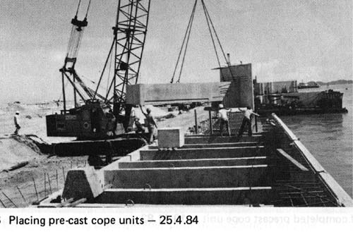
3) The third element is the precast cope piece, which provides the straight front of the wharf with bolt holes and seatings for the fenders. This piece is anchored to the thick part of the deck.
4) The fourth element is the backfill which when compacted gives support to the beam for the inner crane rail.
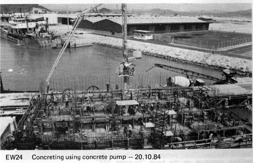
5) The fifth element is the in-situ concrete finishing of the wharf construction. The 2.5m high x 6.Om wide reinforced concrete cap has a service trench Im wide by 0.7m deep.
There is also the crane front rail, and 44 Nos. bollards each 100 tons safe pull, and 51 Nos. Bridgestone cells fenders, 29 C-800 H, 21 Nos. SUC 1250 H, and I No. SUC 2000 H, at the outer corner.

Construction
All the plant was assembled and packed into a dock ship or pontoon transporter. In a single day not unlike an American invasion force during the last war, pontoons came floating off the ship, discharged quickly and disappeared. In this way, a great deal of site preparation work was saved.
At this stage we have to revert to the dredging for the East Wharf trench. It was planned that the dredging should be well ahead of the wharf construction, and stockpiles of sand should be placed away from the trench by pumping sand from nearby Kemaman river. The back-filling of the caisson could then be done when necessary.
A Cutter Suction Dredger (CSD) started in late 1982 dredging the trench but as it turned out, because of the hard ground, the dredgers only just kept ahead of the construction work, and with floating pipe lines and anchors, and siltation caused from various sources and brought together by the monsoon, caused much extra work to the wharf contractor, and brinkmanship remedies had to be used. "Luck" was on our side and the dredging did not hold up the critical path of wharf construction work.
Also the work of placing filter stone and geotextile behind the existing breakwater was tough work taking much time and effort.
The first problem surfaced when the wharf contractor was to take over the first stretch of the trench. The cutter of the CSD had cut down to 1.5m below design dredged level, and left silt on top not being sucked out by the pipes. The silt registered as dredged level on the echo sounder. Further work was required for the adjustment. Anyway, in hard ground this problem proved smaller. But the problem of the silt was there and it had to be removed. The S4, a Trailing Suction Hopper Dredger (TSHD) went in and removed the silt in a difficult operation. The dredging contractor used a 10 in. Toyo silt pump which removed any remaining silt left by the CSD until the more serious siltation problem arose.
Also, at the first stretch only medium hard clay was met with and much deeper dredging was required. So the stone filling under the caisson became at places 7.0m high. The first eleven caissons at the northern end were then placed. To add to the complications, the two caissons i.e. number 15 and 16 below and further out from the stepped foundation level had to be placed before the upper inner caissons No. 14, 13 and 12 could be placed, in order to provide support for the stepped foundation when the inner caissons were filled with sand. This involved complicated planning.
The greatest menace now arose. It was during the N.E. monsoon, and silt from the dredging contractors working bund for placing filter along the existing breakwater was washed into the trench, and all the suspended silt caused by S4's (TSHD) operations in the turning basin was kept in the harbour by the N.E. wind. Also the sand and silt moving from north round the existing breakwater head would have contributed. Much of this silt settled in the trench at rates of 300mm per day causing I to 2m of silt covering the cleaned dredged level, so that stone could not be placed and this work was brought to a stop. At the same time more caissons were cast and it was difficult to "park" these with all the anchors required in the restricted area.
The silt pump proved to be the solution as t could remove silt quickly enough over a sufficiently big area so that the stone could be placed and the screeder frame could work.
A special barge was fitted with two Toyo ten inch silt pumps with their diesel generators, and this barge worked in front of the normal train of crane barge (for receiving stone from supply barges and depositing stone) and the stone spreader barge with the suspended frame.
After some months, the water cleared and the silt pumping could be stopped.
As the caissons were placed on the prepared foundation they were to be filled with sand.
This proved more difficult than expected. A sand stock pile had been made available on land at the filled-in area near the highway, and this was taken by lorry for direct filling, or was taken over the harbour by pontoon and put in by crane. Various pumps, 8 inch and 10 inch pumps were used to take sand from heaps pumped in by the dredging contractor but all not very successful. The final solution was made by a tin mining crew from Perak who used their 8" mining pump and that worked very well.
As the caissons were filled with sand, the backfilling was to be placed up to four caissons from the outer end, so that the sand should not run into the trench.
This was carried out in the following way : the TSHD took sand from the seabed about 5 miles from the coast and dumped this at the eastern side of the turning basin. A CSD then pumped it in through a floating pipeline with discharge northwards, so the sand floated round and along the caissons and actually packed very well. All this called for coordination and cooperation by the two contractors. When the area was nearly filled up, the open end had to be closed. The design was altered to a "rock bund" which was placed between the caissons and the existing breakwater, by another third contractor. So this closing involved cooperation between three main contractors.
The sand pumped in was generally of good quality and packed to readings of static cone of 2 to 4 kg/cm2. Under the crane beam, over a width of 5m, the sand was compacted to a depth of 20m, by using deep vibrocompaction on a triangular pattern of 2.3m.
At the same time the sand pressure on the caissons was decreased. A long cylinder known as vibrofloat, (see details in encl. 115) which were jetted down and then started compaction by big vibrators. As the ground sank around the vibrators, sand was pushed into the voids. The improved cone penetrometer readings were 10.0 - 20.0 MN/M2 or 100- 200 kg./cm2.
After pumping-in of backfill which was thought to be too fine sand with silt and even clayballs, the vibroflot cylinder could not penetrate deeper than 4 - 5m. In an attempt also to compact the layer below, a stone column was to be formed by driving a heavy open ended steel tube and fill it with stone, and then withdraw the tube. However the tube got stuck. When removing the soil inside in order to get the tube deeper, the sand started to heave, so the attempt was called off. However, the Resident Engineer thought that the enormous vibration of the ground caused by the heavy vibratory hammer while driving the solid steel tube into the ground would have consolidated the soil. Check calculations were carried out and the slightly reduced factor of safety, (if any, after the thumping) was accepted.
The deck slab of the wharf was made continuous in order to spread live loads and minimise any effect of weaknesses in the soil. This type of caisson design gives a very durable and sturdy form of wharf.
However, after a long time, the concrete walls might deteriorate, and loss of sand might occur. In order to provide a longer life span a hole in the thick beam was provided over each cell and plugged with lean concrete so that a grout pipe can be easily installed. For the thin deck slab a hole can just be made when required. The caissons can then be turned into solid blocks of grout or concrete.

The durability of a caisson wharf depends also on the sand tightness of the vertical joints and the horizontal stone layer below. This was achieved by filling lean concrete by tremie method in shaped holes, and by geotextile and stone filter.
A big mooring dolphin was placed south of the wharf, and at sea three light beacon structures of tripod design. One extra light beacon structure was added through a very late decision to have an extra beacon. There was only steel tube enough for one pile 1000mm dia. So this was driven vertically. However, the vertical pile might have been hit by a passing vessel or failed in fatigue, although it was well welded and fish-plates added. This pile is at the bottom of the sea, and a light buoy is now placed over the same location instead. Tripods are very much recommended. One of the three has been hit by a vessel but only minor damage occurred.
After the untoward setbacks, operations went smoothly and the original programme could be adhered to including the various dates of entry for the steel plant's unloader, crane and conveyor belt contractor.

The main works were finished a month ahead of time, i.e. end December 1984 which was welcome as the first iron ore carrier was to come in February 1985. The cost of the East Wharf was RM 59.3 million.
March 1987 Original Paper written by KGS, WNF & TYJ of SSP Sdn Bhd
1999 Minor editing by MC Leong
Get a FREE SearchHound Traffic Counter for Your Site |