menu page
link page 2
This item is from Elektor electronics magazine Jan 1985 , the circuit can easily be built on a peice of Veroboard or similar without need of etching a PCB
this entire item can be downloaded from the download section under filename of 'cassface.zip'
Commodore Cassette Interface

Necessity being the mother of invention this circuit was destined
to be designed. The 'necessity' here is Commodore's insistence that the
VIC 20 and C64 computers can only be used with a special cassette recorder
supplied by ... Commodore. One of our designers baulked at the idea of
buying a cassette recorder only for his computer when he already had a
perfectly good audio recorder. Some kindly soul directed his outraged energy
towards the nearest soldering iron and so was born THE Commodore cassette
interface by Elektor.
As in many home computers, the data output by the VIC 20 and C64 via
the cassette interface is in the form of a square wave signal with an amplitude
of 5 Vpp. The information input to the computer has the same form. The
cassette connector also contains a so-called 'sense input' that enables
the computer to check if the recorder's PLAY button is pressed. The Commodore
will only activate its motor output if this is the case. The computer itself
switches the recorder motor on and off and we will see later how this is
actually done. First, however, we must see what happens if the computer
wants to save a file on cassette.
THE interface in detail
The program to be saved appears in the form of pulses with an amplitude
of 5 Vpp on the wnte output of the connector. This amplitude is, of course,
much too large to be saved directly on the tape so the signal is first
reduced to about 200 mV by voltage divider R13/R14. This signal is then
suitable for recording on the tape. The procedure for loading a program
is somewhat more involved. The signal supplied by the recorder via a DIN
or loudspeaker output socket is nowhere near square in shape and its amplitude
is also much too small, at about 200 to 300 mV. The signal must therefore
be amplified and its shape improved. A single op-amp (Al) increases the
signal's amplitude by about six times. The offset of Al, and consequently
of A2, is set to half the supply voltage by means of R3 and R4. The second
op-amp is set up as a schmitt trigger which takes the signal from Al and
forms it into a clean square wave signal with an amplitude of 5 Vpp. The
computer can now load the program via the connector's read input. A LED
(D4) has been included in the circuit to show that this is actually happening.
It will only light when transistor T1 is caused to conduct by a '1' appearing
on its base but the logic levels switch far too fast to be seen with the
naked eye. When data is being transferred the LED appears to be continually
on. One obvious advantage of this LED is that it simplifies finding the
start of a progsm. The motor in the cassette recorder must be switched
on and off at the right times by the computer. Naturally enough this is
done via a relay (Rel) instead of directly. When pin 3 of the connector
goes high transistor T2 is switched on and causes the relay to operate.
First of all, however, the computer must be made to think that the PLAY
button is pressed. This condition is simulated by connecting the sense
input to ground, which is exactly what happens in the Commodore data recorder
when this button is pressed. If the sense input is connected straight to
ground, as we have done, we can then simply forget about it. The power
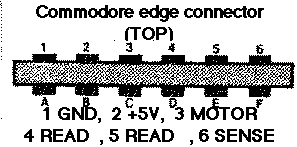
supply for the interface is very kindly provided by the computer. As figures
1 and 2 show, pins 1 and 2 of the cassette connector are GND and + 5 V
respectively. This makes a separate supply for the circuit unnecessary.
The interconnections
Before any data can be transferred all the electronics must be constructed
and all interconnections must be made. A total of six links are needed
at the computer side and the most important point here is to ensure that
none of these are interchanged. The computer would not be very pleased
with this so have a look at figures 1 and 2 to see where everything belongs
before soldenng any wires. The cassette recorder is more tolerant of wrong
connections but it is far better if the circuit works correctly first time.
Again make sure to solder the right wires in the appropnate places. The
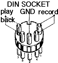
layout usually used for a cassette recorder's DIN socket is illustrated
in figure 3. The two terminals for the relay contacts (points R and S in
figure 1) are linked to the recorder's remote input via a jack plug. If
the tape recorder in question does not have any remote input this is no
reason for panic; simply connect R and S in series in one of the voltage
supply lines to the motor.
Installation and use
All the components must be fitted to the printed circuit board shown
in figure 4 and when this is done a suitable case must be found for the
circuit. Alternatively, it may be possible to include it within the cassette
recorder case. Whichever of these is chosen there is one point to bear
in mind: the connecting wires must not be made too long. A special connector
is needed to link the interface to the computer's cassette input/output
lines. This is a six-way printed circuit board connector with a spacing
of 3.96 mm (0.156") between the pins. The wires can also be soldered directly
onto the printed circuit board. We will be very brief in our instructions
on using the circuit: refer to page 18 of the C64 user's manual. The function
of Sl in the circuit is clear. It is used to switch the motor on and off,
which is very handy for winding the tape. If an error message is generated
during loading the volume control on the cassette recorder is probably
not correctly set. When reading tapes that you have not recorded yourself
it may be necessary to re-align the record/playback head. If our experiences
with this interface are anything to go by, however, errors will rarely
occur, even when 'turbo' loading.
Parts list
Resistors:
R 1, R2 = 4k7
R3, R4 = 2k2
R5, R8 = 22 k
R6, R11, R16 = 47 k
R7, R10, R15 = 10 k
R9 = 20 k
R12 = 20 ohms
R13 = 100 ohms
R14 = 1k5
Capacitors:
C1 = 10 n
C2 = 22 n
C3 = 22microfarad /16 V
C4 . . C7 = 100 n
C8 = 10 microfarad/16 V
Semiconductors:
D1, D2 = AA119
D3, D5 = 1N4148
D4 = LED
T1, T2 - BC547 B
IC1 - LM387
Miscellaneous:
Re1 = relay, 6 V PCB mounting type (MS Components part no. 8055)
S1 - single-pole toggle switch 6-way PCB edge connector with pin spacing
of 3.96 mm (0.156" Maplin, order no. FG24B)
 |
 |
 |
|
PCB FRONT - save and print out at 90% |
PCB REAR - save and print out at 90% |
|---|
 |
 |